Active antenna arrays

a technology antenna arrays, applied in the field of active antenna arrays, can solve the problems of cost and general inconvenience, and achieve the effect of reducing the hardware, weight, cost and complexity required for an aaa to operate with different mobile telecommunications systems

Active Publication Date: 2014-02-06
ALCATEL LUCENT SAS
View PDF9 Cites 23 Cited by
  • Summary
  • Abstract
  • Description
  • Claims
  • Application Information

AI Technical Summary

Benefits of technology

[0013]In at least an embodiment of the invention, the efficient design of multi-band (multi-band is the commonly used term for multiple mobile telecommunication systems) active antenna arrays (AAA) is based on the fact that the total number of RF transceivers required for the synthesis of multi-band AAA can be reduced by employing one transceiver of each band / system to feed multiple antenna elements through either a passive or an active feeding network. Therefore an advantage arises in that the amount of hardware, weight, cost and complexity required for an AAA to operate with different mobile telecommunications systems can be reduced where RF transceivers of each band of the AAA coupled to the antenna elements are not allocated on a one to one basis, but instead a phase shifting and feeding (multiplexing / demultiplexing) network is provided so that each transceiver is coupled to more than one antenna element. Although this may result in some diminution in quality in some situations, it has been found that in the majority of practical situations encountered, a diminution in quality is not significant.

Problems solved by technology

This might require separate antenna array configurations for each system, which is clearly costly and generally inconvenient

Method used


Image

  • Active antenna arrays
  • Active antenna arrays
  • Active antenna arrays

Examples


Embodiment Construction

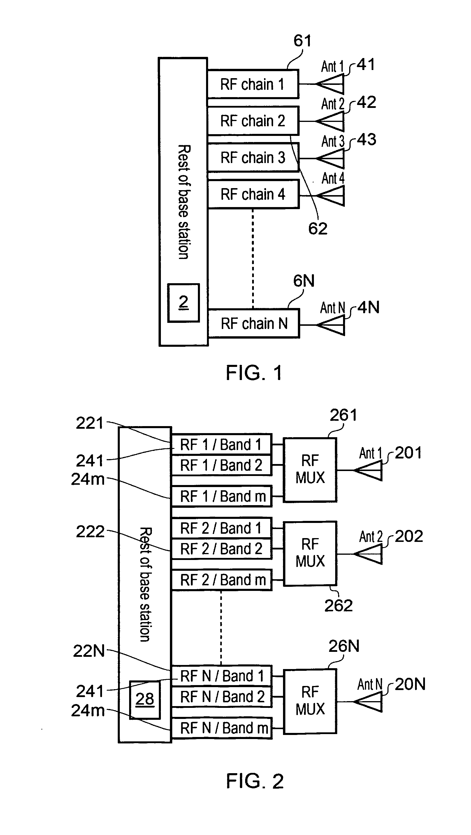
[0031]A design of a multi-band (m-band) AAA BS is shown in FIG. 2, for explanation of this invention (in this specification the term “band” is used to denote a mobile telecommunications system, in accordance with common parlance). N antenna elements 201 . . . 20N are provided, the same number as in FIG. 1. Each antenna element is fed from a set 22 . . . 22N, each set comprising m dedicated RF front-ends (transceivers) 24 . . . 24m, each front-end designed to operate on a different band / system. Thus it may be seen that the total number of transceivers is also divided into m groups, each group operating on a respective system. Each feed set 221 . . . 22N is fed through a respective multiplexing network 261 . . . 26N to a respective antenna element 201 . . . 20N. The rest of the base station is indicated at 28.

[0032]Each transceiver 241 . . . 24m is commonly provided with a transmit path which includes a digital to analog converter DAC, a frequency up-conversion stage and a power ampli...


PUM


Abstract

In order to reduce the weight, cost and complexity of an active antenna array, designed for use with a plurality of different mobile telecommunications systems (multi-band system), the array comprises a plurality of antenna elements, which are divided into a plurality of antenna groups; a plurality of RF transceivers, which are divided into transceiver sets, wherein each transceiver of a set is arranged to operate on a different mobile telecommunications system, and including respective phase shifting and feeding networks coupled between each transceiver set and a respective antenna group, so that each transceiver of a set is coupled to each antenna element of the respective antenna group.

Description

FIELD OF THE INVENTION[0001]The present invention relates to active antenna arrays for mobile telecommunications systems.BACKGROUND ART[0002]Active Antenna Arrays (AAA), otherwise known as smart antennas, have recently gained popularity as candidate technology for base stations (BS) of future cellular / mobile networks. In the context of AAA, each radiator of the BS antenna array is fed by a dedicated RF transceiver / RF front-end, as shown in FIG. 1. In FIG. 1, a base station 2 has an active antenna array comprising a series of N antenna elements 41 . . . 4N, each being coupled to a respective RF transceiver 61 . . . 6N. Typically each RF transceiver comprises a transmit path which includes a digital to analog converter DAC, a frequency up-conversion stage and a power amplifier PA, and a receive path which includes a low noise amplifier, a frequency down-conversion stage and an analog to digital converter ADC. Appropriate phase shifts are applied, either in the transceivers, or in bas...

Claims


Application Information

Patent Timeline
Patent Type & Authority Applications(United States)
IPC IPC(8): H04W88/10H01Q5/50
CPCH04W88/10H01Q1/246H01Q21/06H04B1/0057H01Q5/50H01Q21/00H04B1/00
Inventor KOKKINOS, TITOSPIVIT, FLORIAN
Owner ALCATEL LUCENT SAS
Why Eureka
Try Eureka