Angle Inclining Structure for a Desk

a desk and angle inclination technology, applied in the direction of drawing desks, stand/trestles, kitchen equipment, etc., can solve the problem that the table cannot be fixed safely, and achieve the effect of safe positioning function

Inactive Publication Date: 2014-02-20
SING BEE ENTERPRISE
View PDF30 Cites 23 Cited by
  • Summary
  • Abstract
  • Description
  • Claims
  • Application Information

AI Technical Summary

Benefits of technology

[0005]The primary object of the present invention is to provide an angle inclining str

Problems solved by technology

However, the plate still

Method used


Image

  • Angle Inclining Structure for a Desk
  • Angle Inclining Structure for a Desk
  • Angle Inclining Structure for a Desk

Examples


Embodiment Construction

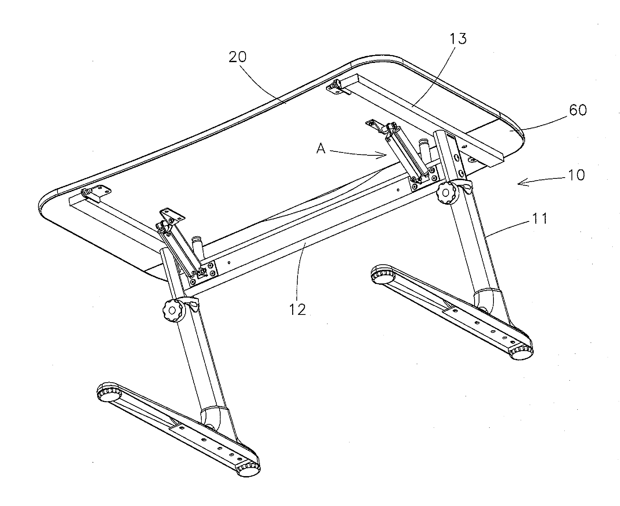
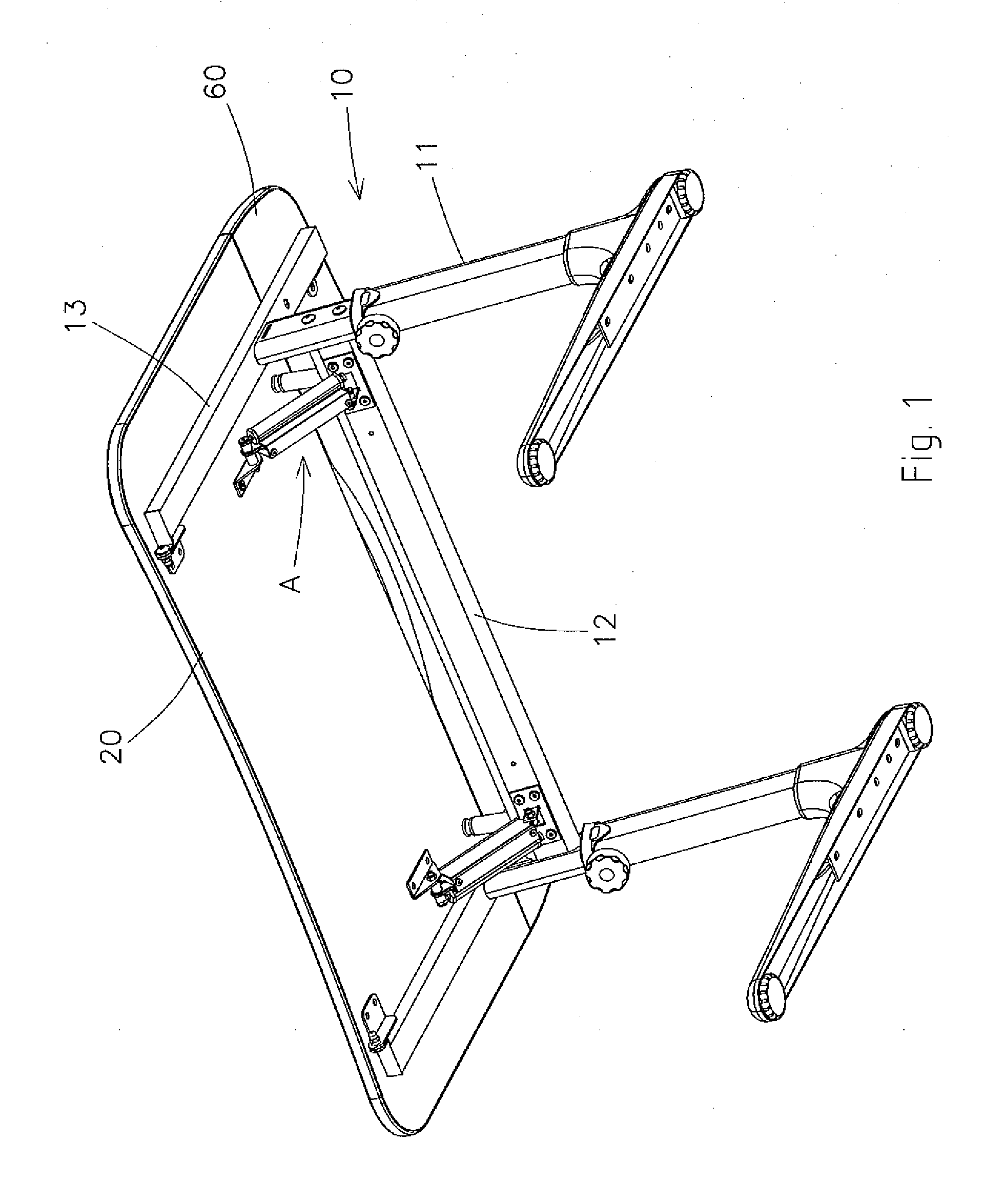
[0023]FIGS. 1 to 10, an angle inclining structure for a desk comprises a body 10 and an angle inclining structure A. The body 10 includes two opposite support legs 11, a horizontal rod 12 fixed between the two opposite support legs 11, two support posts 13 connected with two top ends of the two support legs 11 and a first plate 20, wherein the angle inclining structure A is disposed between the horizontal rod 12 and the first plate 20.

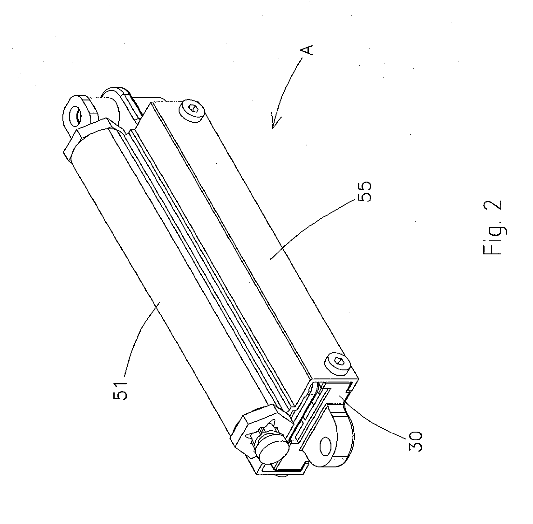
[0024]It is to be noted that the angle inclining structure A is comprised of a holder 30, a covering member 40, and a buffer member 50. The holder 30 includes a locking tab 31 extending outwardly from one end thereof and axially connecting with the horizontal rod 12, a receiving room 32 and a groove 33, both of which are defined on a top surface of the holder 30, wherein the receiving room 32 is used to receive a retainer 34 with a boss 341 and a pushing element 35 for pushing the retainer 34, and the groove 33 is applied to receive a positioning membe...


PUM


Abstract

An angle inclining structure for a desk contains a body and an angle inclining structure, the body including two opposite support legs, a horizontal rod, and two support posts connected with the two support legs and a first plate, wherein the angle inclining structure is disposed between the horizontal rod and the first plate and has a holder, a covering member, and a buffer member, the holder includes a locking tab and connects with the horizontal rod, a receiving room to receive a retainer and a pushing element, and a groove to receive a positioning member; the covering member includes a slot, plural tilted recesses, and a locking hole; a free end of the buffer member axially couples with one end of the covering member and a bottom surface of the first plate so that when the first plate axially rotates upwardly, the covering member slides on the holder.

Description

FIELD OF THE INVENTION[0001]The present invention relates to an angle inclining structure, and more particularly to an angle inclining structure for a desk which has a slow descending function and a safe positioning function.BACKGROUND OF THE INVENTION[0002]A conventional angle inclining structure for a desk is capable of adjusting an inclined angle of a plate of a desk, but it does not have a descending function. Therefore, when a user is desired to move the plate back to an original position after the plate is moved upwardly, the plate is manually pressed downward by the user, yet noises generate and the user is clamped by the plate easily.[0003]To obtain a descending purpose, a hydraulic rod of a buffer structure is fixed on a bottom end of the plate so that the plate is adjusted toward a desired angle and is descended slowly. However, the plate still can not be fixed safely.[0004]The present invention has arisen to mitigate and / or obviate the afore-described disadvantages.SUMMAR...

Claims


Application Information

Patent Timeline
IPC IPC(8): A47B13/02
CPCA47B13/088A47B27/18A47B41/02A47B2200/0026A47B2200/0043
Inventor TSAI, CHI-CHENG
Owner SING BEE ENTERPRISE
Why Eureka
Try Eureka