
Measuring head for a coordinate measuring machine for determining spatial coordinates on a measurement object

Active Publication Date: 2014-02-27
CARL ZEISS IND MESSTECHN GMBH
View PDF4 Cites 26 Cited by
  • Summary
  • Abstract
  • Description
  • Claims
  • Application Information

AI Technical Summary

Benefits of technology

The patent describes a new measuring head that has a breaking point in the tool that can separate from the measuring head in case of a collision. This is different from previous measuring heads that had the breaking point in the measuring head. This new design may not be protected against damage in a collision, but it allows for easier and more stable production of the measuring head. The sliders in the measuring head have a simple design that allows for easy manual or machine actuation of the locking mechanism. This refinement makes use of the measuring head more intuitive and reliable.

Problems solved by technology

It has been found that the separable implementation of the retaining pin is unfavorable if the retaining pin also serves for rotating the probe tool and therefore has to absorb torques during the rotation.
A suitable two-part or multipart realization of the retaining pin is complicated and expensive, especially if the probe head additionally needs to be lightweight and compact.

Method used


Image

  • Measuring head for a coordinate measuring machine for determining spatial coordinates on a measurement object
  • Measuring head for a coordinate measuring machine for determining spatial coordinates on a measurement object
  • Measuring head for a coordinate measuring machine for determining spatial coordinates on a measurement object

Examples


Embodiment Construction

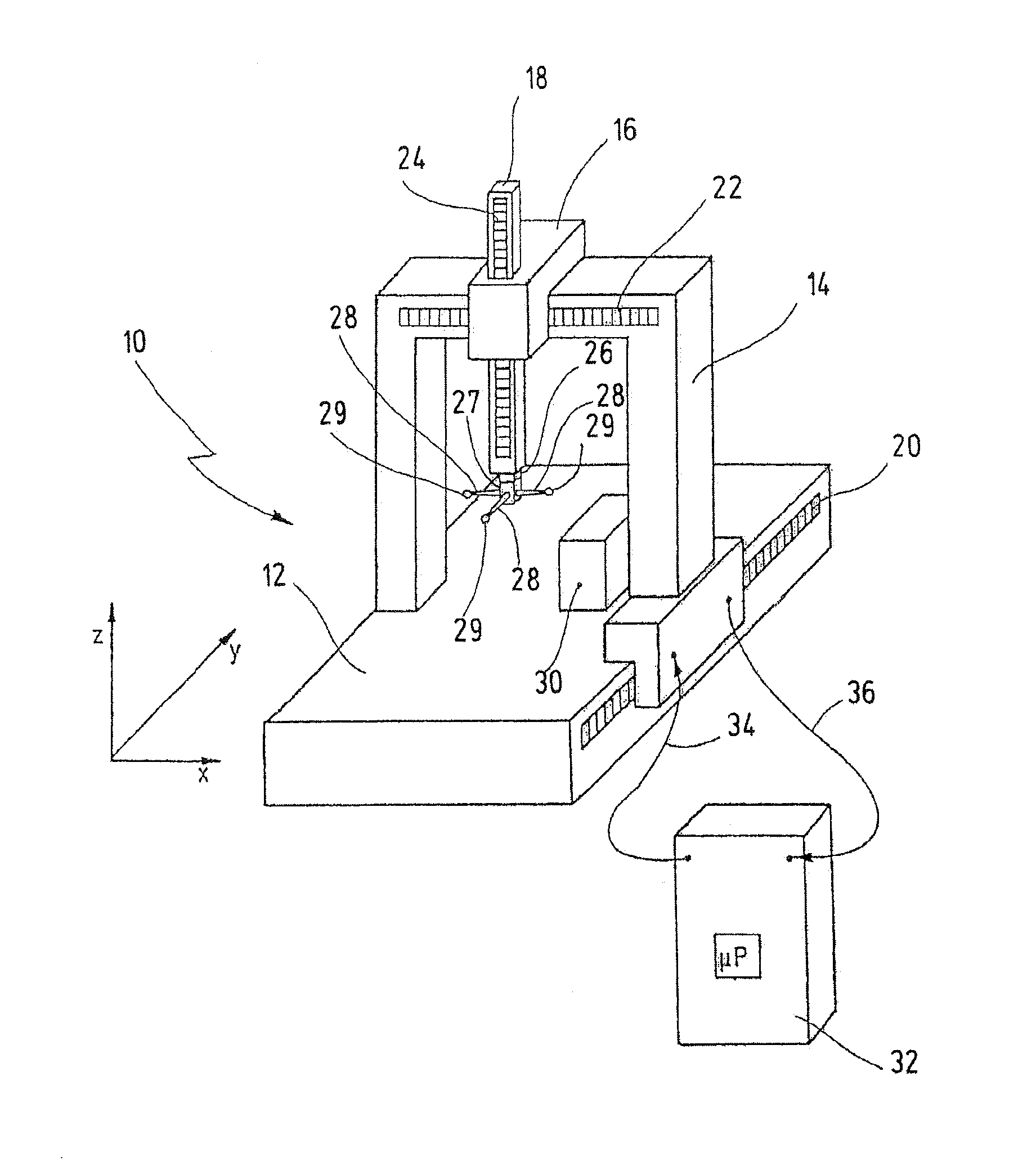
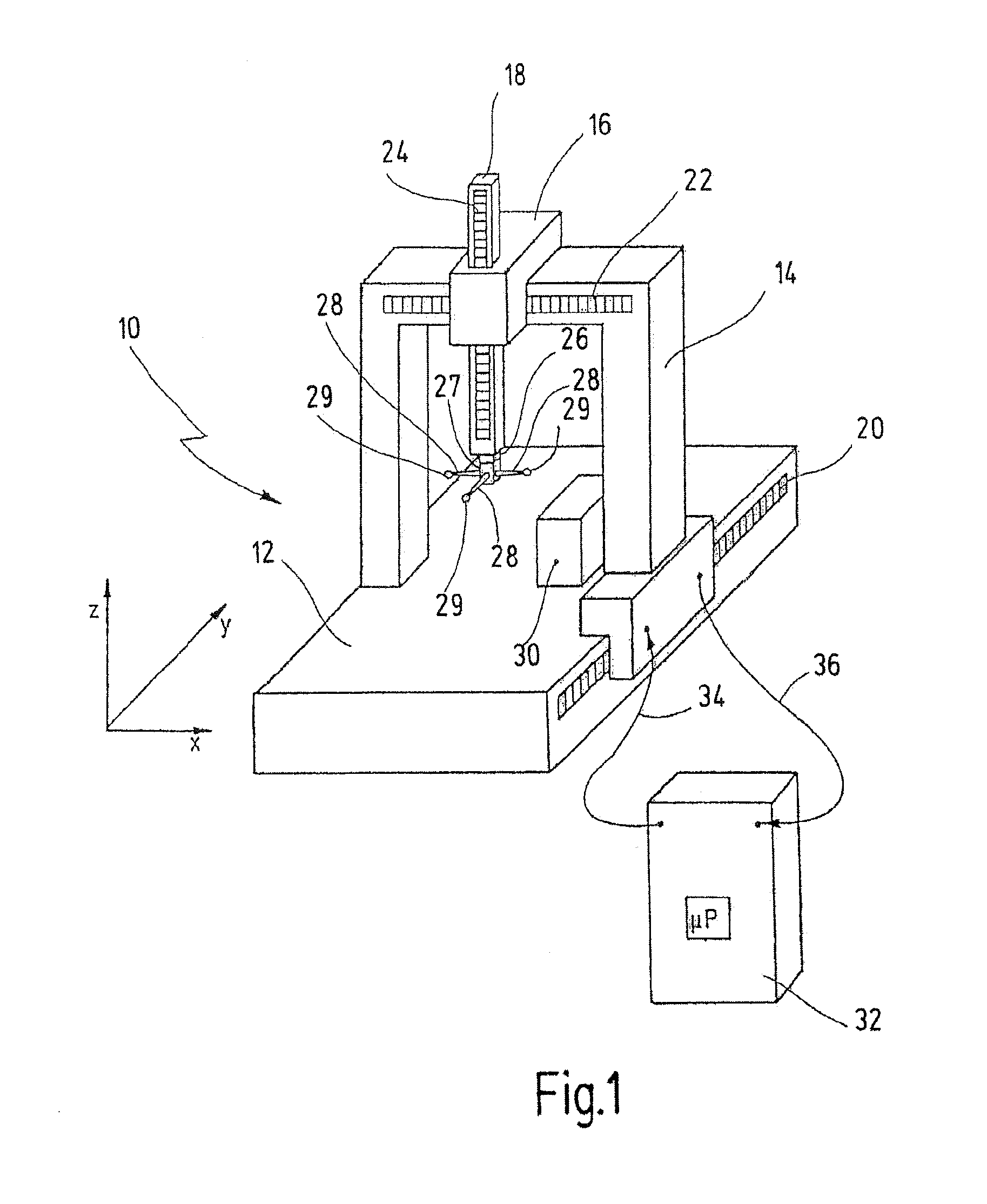
[0056]In FIG. 1, a coordinate measuring machine having the novel probe head is designated overall with the reference numeral 10. The coordinate measuring machine 10 here has a base 12, on which a portal 14 is arranged so as to be moveable in the longitudinal direction. The movement direction of the portal 14 relative to the base 12 is generally referred to as the Y axis. Arranged on the upper cross member of the portal 14 is a carriage 16, which is displaceable in the transverse direction. The transverse direction is usually referred to as the X axis. The carriage 16 carries a quill 18, which can be moved in the Z direction, i.e. perpendicular to the base 12. Reference numerals 20, 22, 24 designate measurement scales, which can be used to determine the position of the portal 14, of the carriage 16 and of the spindle 18. The measurement scales 20, 22, 24 are typically glass measurement scales which are read using suitable sensors.

[0057]Arranged on the lower free end of the quill 18 i...


PUM


Abstract

A measuring head for a coordinate measuring machine for determining spatial coordinates on a measurement object has a coupling part for detachably receiving a measurement tool. The coupling part has a number of first bearing elements, a magnet and a retaining pin. The measurement tool has a disk with a number of second bearing elements, an anchoring plate and at least one adjustable locking element. The magnet is configured to attract the anchoring plate so as to bring the first and second bearing elements into engagement with one another. The first and second bearing elements, in the engaged state, define a defined position of the measurement tool on the coupling part. The at least one locking element secures the measurement tool to the retaining pin. The anchoring plate is detachably secured to the disk and the at least one locking element retains the anchoring plate on the retaining pin.

Description

CROSSREFERENCES TO RELATED APPLICATIONS[0001]This application is a continuation of international patent application PCT / EP2012 / 057349 filed on Apr. 23, 2012 designating the U.S., which international patent application has been published in German language and claims priority from German patent application DE 10 2011 100 467.3 filed on May 2, 2011. The entire contents of these priority applications are incorporated herein by reference.BACKGROUND OF THE INVENTION[0002]The present invention relates to a measuring head for a coordinate measuring machine and to a measurement tool for such a measuring head.[0003]Coordinate measuring machines are typically used for determining geometric dimensions or even the physical shape of workpieces. A coordinate measuring machine typically has a measuring head, which can be moved relative to the workpiece (called measurement object further down below). Depending on the position of the measuring head relative to the workpiece, spatial coordinates can ...

Claims


Application Information

Patent Timeline
IPC IPC(8): G01B5/008
CPCG01B5/008G01B5/012
Inventor BRENNER, KURTJENISCH, WALTERWOLETZ, TOBIASKAUFMANN, DIETER
Owner CARL ZEISS IND MESSTECHN GMBH
Learn More