Thermal management systems and methods

a management system and management system technology, applied in the field of thermal management systems and methods, can solve the problems of not being able to adjust to outside temperatures, using frozen ice to protect products that cannot be exposed, and negative twenty degrees celsius may not be ideal,

Inactive Publication Date: 2014-02-27
PELICAN BIOPHARMA
View PDF9 Cites 41 Cited by
  • Summary
  • Abstract
  • Description
  • Claims
  • Application Information

AI Technical Summary

Benefits of technology

[0029]In some embodiments, at least one of the inner panels includes a raised portion provided on an inner surface of the at least one of the inner panel. A surface of the raised portion defines a portion of the second non-linear path.
[0030]A method of manufacturing a thermal management system includes (but is not limited to any one or combination of): (i) providing a case; (ii) providing an insulation material within the case, the insulation material defining an interior volume; (iii) arranging a liner in the interior volume of the insulation material, the liner defining an interior volume; (iv) providing an outer container of phase change material in the interior volume of the liner, the outer container defining an interior volume; the outer container comprising a plurality of outer panels containing a first phase change material, the plurality of outer panels comprising a botto...

Problems solved by technology

Using frozen ice to protect a product that cannot be exposed to, for example, negative twenty degrees Celsius may not be ideal because no phase change will occur in the ice from zero degrees Celsius to negative twenty degrees Celsius.
Typical “passive” systems are not able to adjust to outside temperatures in order to maintain the appropriate temperature range.
However, the frozen ice would not protect against a negative ten-degree temperature.
However, the fact that a frozen and refrigerated water shipper is excellent for zero degrees Celsius means that it may not be suita...

Method used


Image

  • Thermal management systems and methods
  • Thermal management systems and methods
  • Thermal management systems and methods

Examples


Embodiment Construction

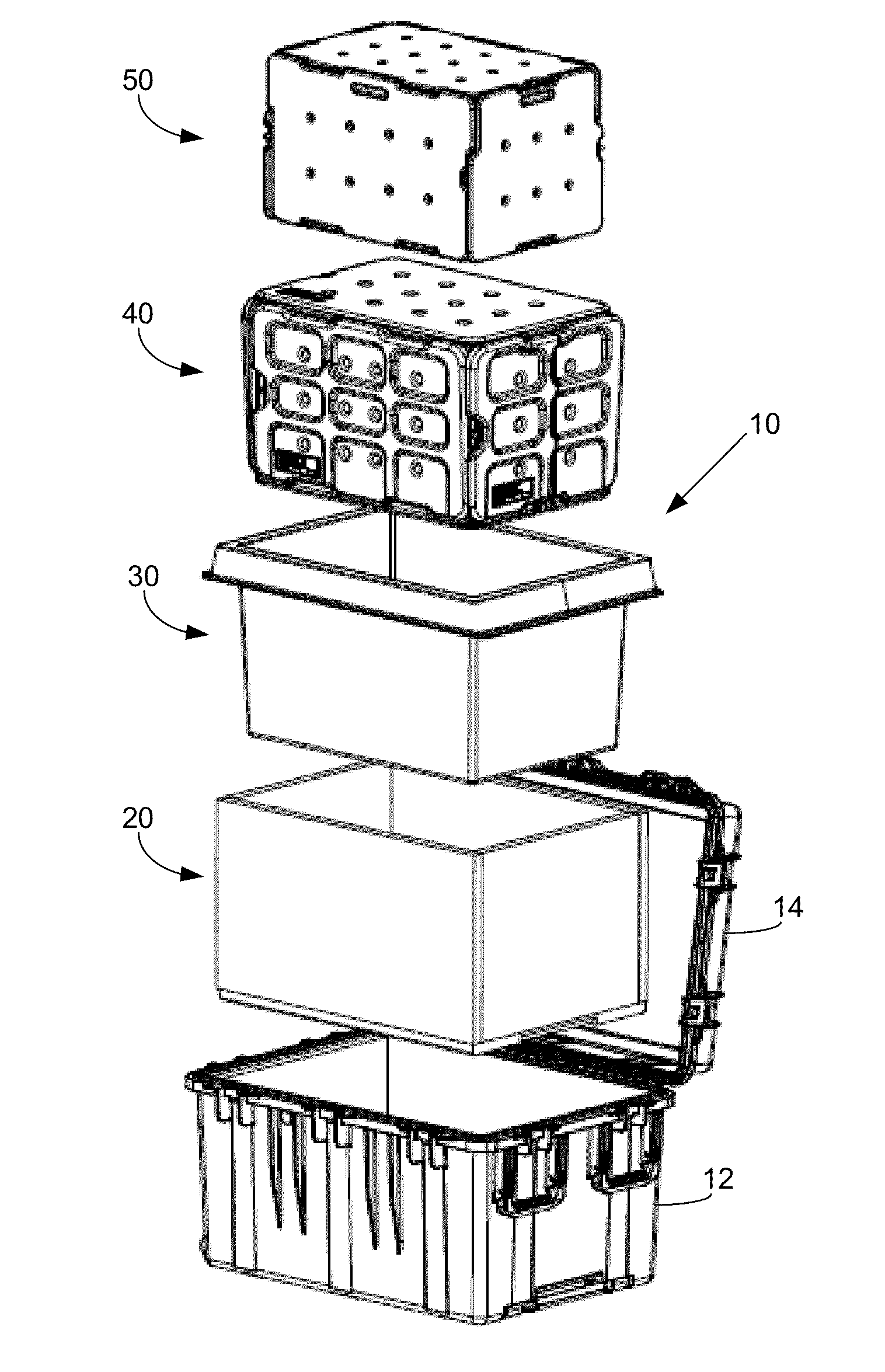
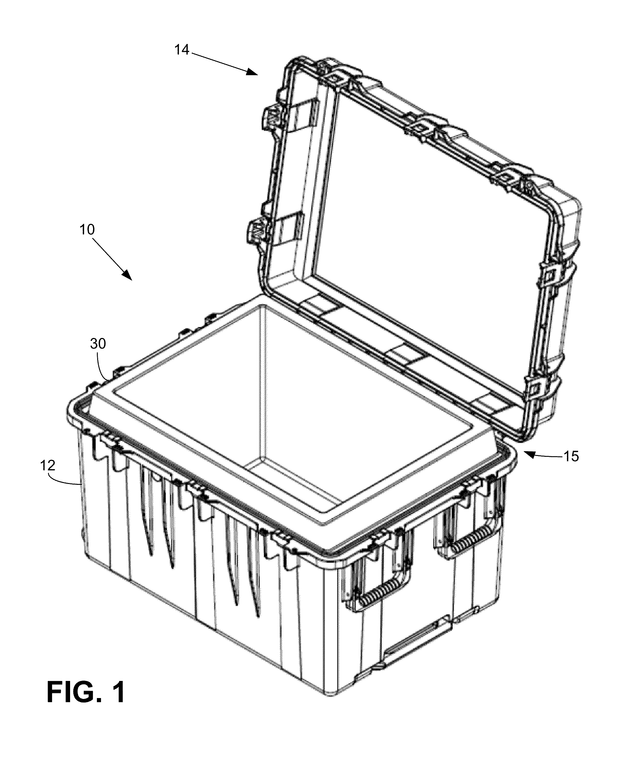
[0041]FIG. 1 illustrates a thermal management case 10 according to various embodiments. The case 10 may be made of any suitably rigid material (e.g., plastic, metal, composite materials, resins, etc.). The case 10 includes a base 12 for receiving one or more articles and a lid 14. In some embodiments, the lid 14 may be operatively connected to the base 12 (e.g., via a hinge member, latches, clip members, or the like).

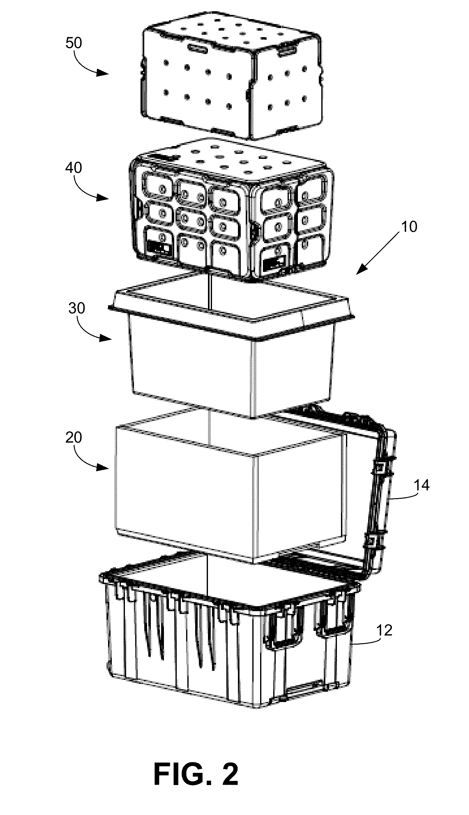
[0042]FIG. 2 illustrates an exploded view of the case 10. An insulation material, such as VIP subassembly 20, may be arranged within the base 12. A liner 30 may be provided in the VIP-subassembly 20. One or more layers of panels of phase change material (PCM) may be provided in the liner 30. In particular embodiments, an outer container 40 of panels of PCM may be provided in the liner 30. An inner container 40 of panels of PCM may be provided in the inner container 30.

[0043]FIGS. 3A and 3B illustrate cross-section views of the case 10. With reference to FIGS. 1-3B, in v...


PUM

PropertyMeasurementUnit
Thicknessaaaaaaaaaa
Phaseaaaaaaaaaa

Abstract

A thermal management system includes a case; an insulation material provided within the case, the insulation material defining an interior volume of the insulation material; a liner arranged in the interior volume, the liner having an inner surface that extends toward a center of the case; an outer container of phase change material provided in the liner, the outer container comprising a plurality of outer panels containing a first phase change material, the plurality of outer panels comprising a bottom outer panel, a top outer panel, and side outer panels; and an inner container of phase change material provided in the outer container, the inner container comprising a plurality of inner panels containing a second phase change material; wherein an outer surface of each of the side outer panels is parallel with the inner surface of the liner.

Description

TECHNICAL FIELD[0001]The disclosure relates generally to the field of thermal management systems and methods, and, in particular, to phase change material systems and methods.BACKGROUND[0002]Passive shippers typically use a phase change material (PCM) that changes from solid to liquid and vice versa (e.g., ice to water and water to ice), where the PCM's temperature changes minimally while the PCM absorbs or releases energy due to external / internal temperature differential. This is how ice is able to maintain a beverage cold, by absorbing heat from the beverage (which itself is absorbing heat from the environment or the user's hand) while the ice turns into a liquid (at zero degrees Celsius / thirty-two degrees Fahrenheit). This is also how commonly available water-based gel packs or packets are able to maintain temperatures near zero degrees Celsius inside of an insulated lunch box or camping cooler.[0003]The term “passive” is used in “passive shippers” because these types of systems ...

Claims


Application Information

Patent Timeline
IPC IPC(8): B65D81/18B23P19/04
CPCF25D3/08F25D2303/0843F25D2303/0844F25D2303/0845F25D2201/14Y10T29/49826Y10T29/4935F25D2303/085F25D2303/08222B23P15/26F25D11/003
Inventor PATSTONE, CHRISTOPHER H.
Owner PELICAN BIOPHARMA
Why Eureka
Try Eureka