
Patsnap Eureka
For R&D, Patsnap Eureka makes reading and utilizing patents & technical documents easy.
Patsnap Eureka AIR
Designed for self-driven R&D workflows. Generate viable solutions, solve complex R&D challenges, empower your innovation with AI.

Patsnap Eureka Materials
Designed for material experts only. Revolutionize your material R&D, from search, analyze, to developing new materials.

TechResearch
Generate reliable direction feasibility study reports for your R&D in just a few steps.

TechSeek
Discover and master advanced knowledge NOW. Basics, ideas, possibilities, all at once.

TechMind
As an expert in R&D Theories, TechMind can generates customized viable solutions instantly.

TechRisk
Analyze your overall solution with one click, know your potential R&D risks in advance.

TechMonitor
Get weekly tech updates, stay abreast of the latest tech innovations and key insights.
Robot
a robot and robot technology, applied in the field of robots, can solve the problems of large amount of calculations, slow response speed, and easy generation of vibration in the arm link portions, and achieve the effects of increasing the response speed of the robot control, and reducing the amount of calculations
- Summary
- Abstract
- Description
- Claims
- Application Information
AI Technical Summary
Benefits of technology
Problems solved by technology
Method used
Image

Examples
first embodiment
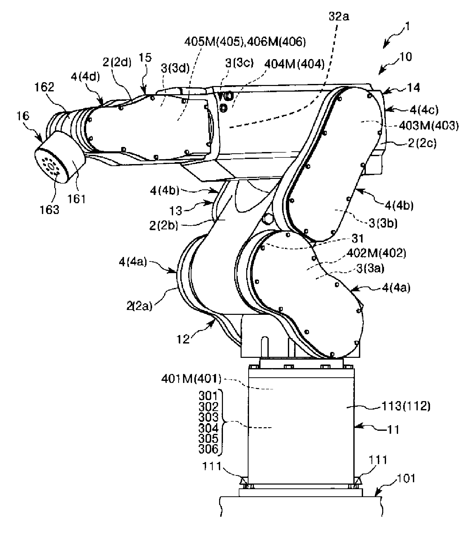
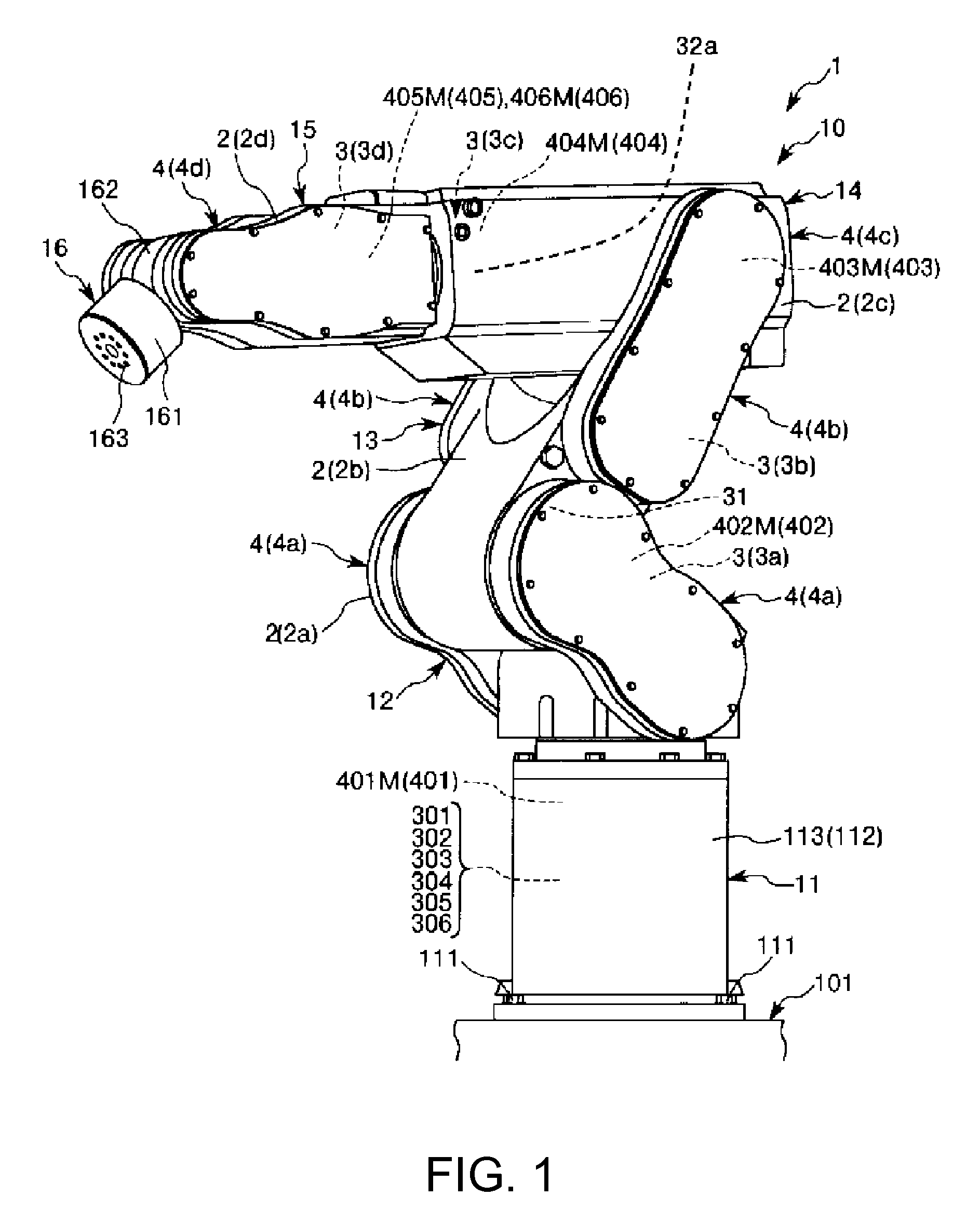
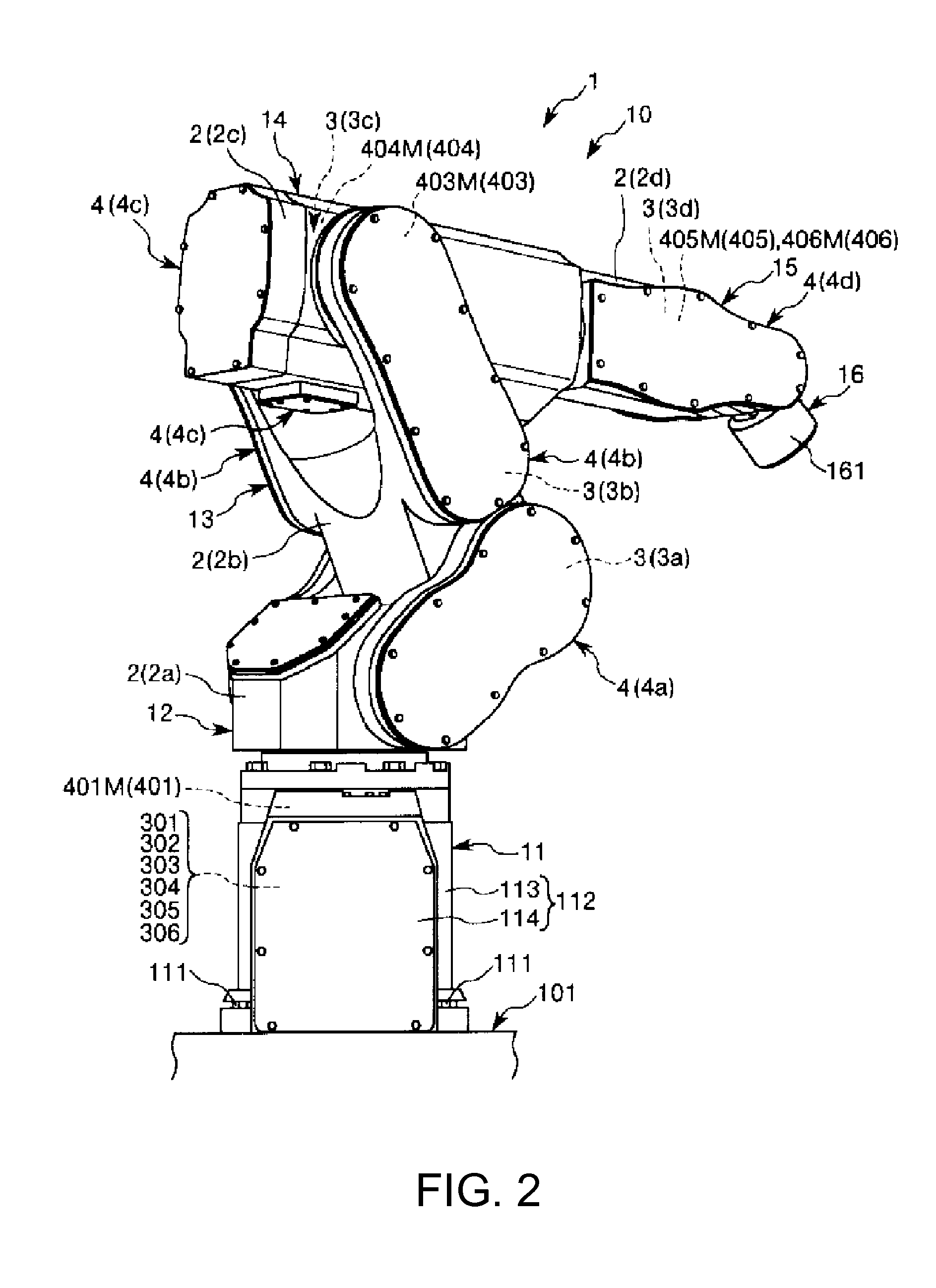
[0081]FIG. 1 is a perspective view when a first embodiment of a robot is viewed from the front side. FIG. 2 is a perspective view when the robot shown in FIG. 1 is viewed from the back side. FIGS. 3 and 4 are schematic views of the robot shown in FIG. 1, respectively. FIG. 5 is a block diagram of main portions of the robot shown in FIG. 1. FIGS. 6 to 10 are block diagrams of the main portions of the robot shown in FIG. 1, respectively.
[0082]In addition, in the following, for convenience of description, the upper side in FIGS. 1 to 4 and FIG. 6 is referred to as “upper” and “upside” and the lower side is referred to as “lower” and “downside”. Additionally, the base side in FIGS. 1 to 4 is referred to as a “base end”, and the opposite side is referred to as a “tip”. Additionally, rotation axes O2 and O3 are shown in an exaggerated manner in FIG. 4, respectively. Additionally, inertia sensors 31 and 32a are shown outside arms 12 and 14 in FIG. 4, respectively, in order to clarify the p...
second embodiment
[0162]FIG. 11 is a block diagram showing main portions of a second embodiment of a robot.
[0163]The second embodiment will be described below mainly, regarding the differences from the aforementioned first embodiment, and the description of the same matters will be omitted.
[0164]As shown in FIG. 11, in the robot 1 of the second embodiment, the second drive source controller 202 and the third drive source controller 203 of the control device 20 are different from those of the first embodiment, respectively. That is, in the robot 1, the operation of the first drive source 401 and the third drive source 403 is controlled on the basis of the detection results of the first inertia sensor 31 and the second (a) inertia sensor 32a. The second drive source controller 202 and the third drive source controller 203 will be described below.
[0165]As shown in FIG. 11, the second drive source controller 202 has a subtractor 517, a position controller 527, a subtractor 537, an angular velocity contro...
third embodiment
[0189]FIG. 12 is a schematic view showing a third embodiment of a robot. FIGS. 13 and 14 are block diagrams of main portions of the robot shown in FIG. 12, respectively.
[0190]In addition, in the following, for convenience of description, the upper side in FIG. 12 is referred to as “upper” and “upside” and the lower side is referred to as “lower” and “downside”. Additionally, the base side in FIG. 12 is referred to as a “base end”, and the opposite side is referred to as a “tip”. Additionally, the rotation axes O2 and O3 are shown in an exaggerated manner in FIG. 12, respectively.
[0191]Additionally, inertia sensors 31 and 32b are shown outside arms 12 and 13 in FIG. 12, respectively, in order to clarify the presence of the sensors.
[0192]The third embodiment will be described below, mainly regarding the differences from the aforementioned first embodiment, and the description of the same matters will be omitted.
[0193]As shown in FIG. 12, in the robot 1 of the third embodiment, the sec...
PUM
 Abstract
Description
Claims
Application Information
 - R&D Engineer
- R&D Manager
- IP Professional
- Industry Leading Data Capabilities
- Powerful AI technology
- Patent DNA Extraction
Browse by: Latest US Patents, China's latest patents, Technical Efficacy Thesaurus, Application Domain, Technology Topic, Popular Technical Reports.
© 2024 PatSnap. All rights reserved.Legal|Privacy policy|Modern Slavery Act Transparency Statement|Sitemap|About US| Contact US: help@patsnap.com