Robot

a robot and robot technology, applied in the field of robots, can solve the problems of slow response speed, easy generation of vibration in the arms, and huge amount of calculations, and achieve the effects of improving response speed in the control of the robot, and reducing the amount of calculations

Active Publication Date: 2015-05-19
SEIKO EPSON CORP
View PDF17 Cites 18 Cited by
  • Summary
  • Abstract
  • Description
  • Claims
  • Application Information

AI Technical Summary

Benefits of technology

[0012]With this configuration, the vibration in the robot can be easily and reliably suppressed.
[0057]That is, a calculation for performing feedback to the controller on the basis of huge information is unnecessary, and thereby, the response speed in the control of the robot can be increased. Additionally, since a calculation in which a singular point is present is unnecessary, the control of the robot can be reliably performed, and vibration can be reliably suppressed. In addition, when one inertia sensor and one angle sensor may be provided so as to correspond to every orthogonal rotation axis, and a plurality of parallel rotation axes are present, one rotation axis of them may be selected from a rotation axis orthogonal to the one rotation axis, and one inertia sensor and one angle sensor may be provided for these rotation axes, respectively.

Problems solved by technology

A multi-axis robot that includes a base and a plurality of rotatable arms and that works freely in a three-dimensional space has a problem in that vibration is easily generated in the arms due to the rotation of the arms or the disturbance applied to the arms.
At this time, since it is necessary to perform a coordinate axis transformation referred to as the Jacobi's transformation, and a matrix calculation having a number of sine and cosine factors is required, the amount of calculations becomes huge.
Accordingly, there is a drawback in that the response speed becomes slow.
Additionally, since accurate acceleration or speed cannot be fed back if calculation precision declines, vibration suppression capability may decline or control performance may be impaired.
Accordingly, even if this technique is adopted for a multi-axis robot in which the rotation axes of the arms are different from each other, vibration suppression capability cannot be satisfied.
That is, when the angle θ formed between the axis of the second arm and the axis of the third arm is smaller than the first threshold or larger than the second threshold, the inertia moment of the robot is small and the vibration in the robot is small but control tends to become unstable and the robot vibrates easily, compared to a case where the angle θ formed between the axis of the second arm and the axis of the third arm is equal to or larger than the first threshold and equal to or smaller than the second threshold.

Method used


Image

  • Robot
  • Robot
  • Robot

Examples


first embodiment

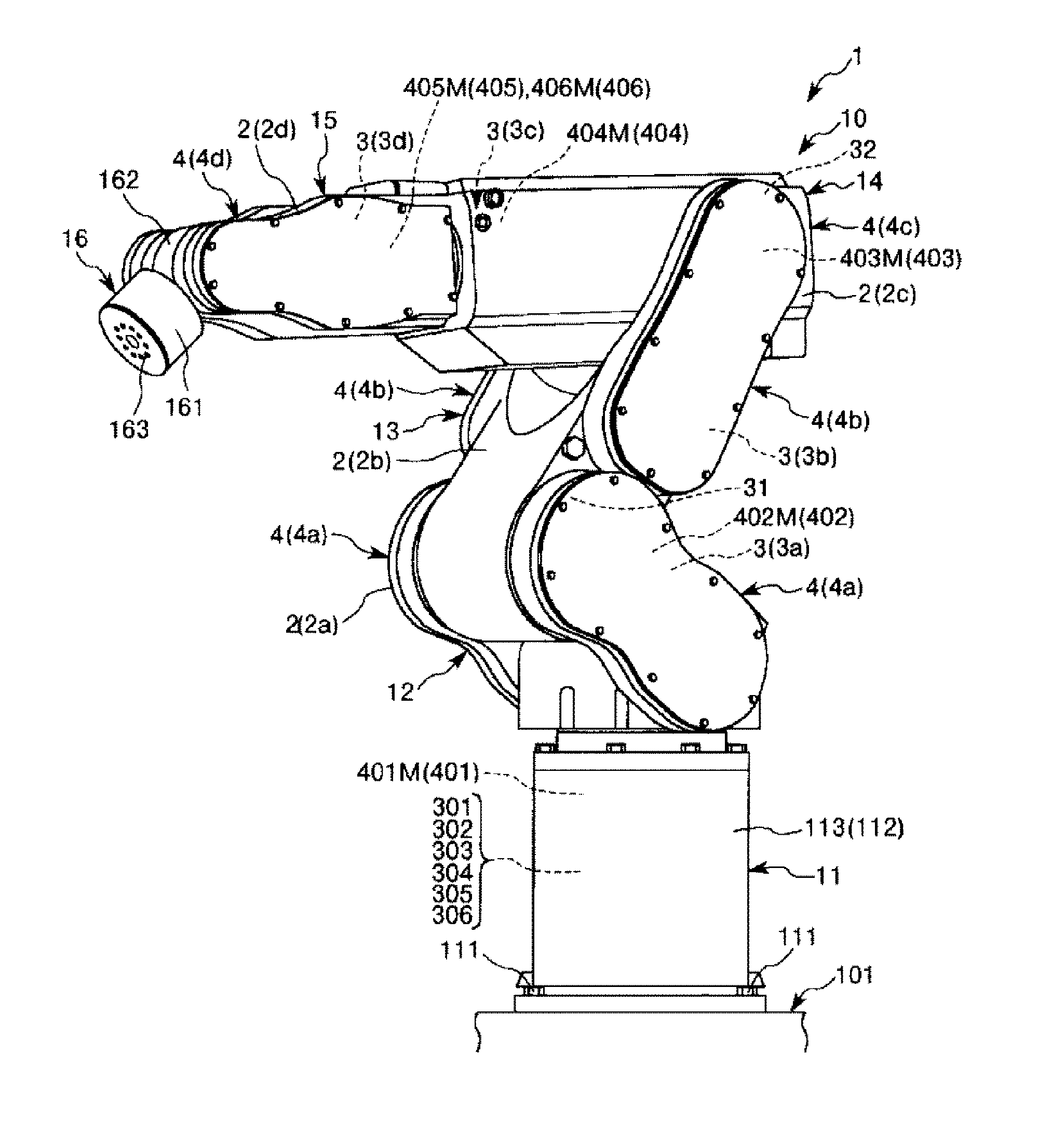
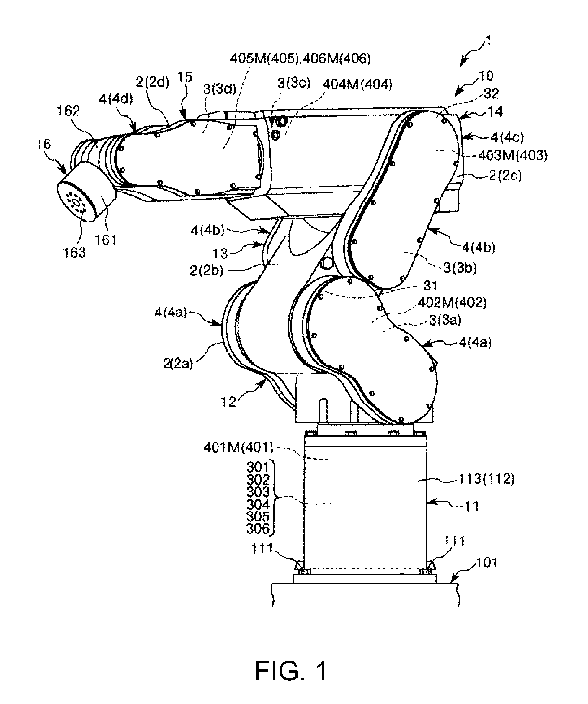
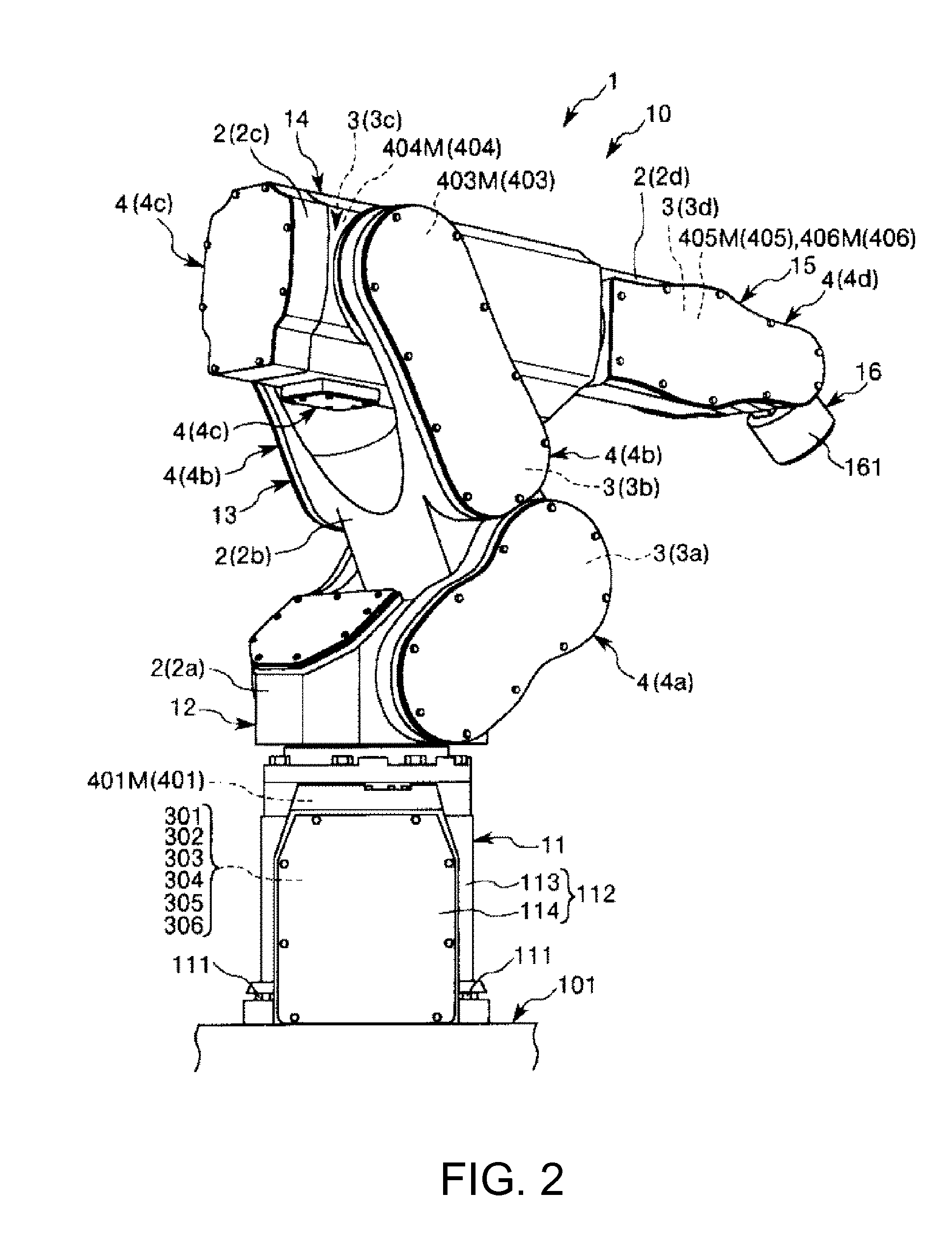
[0077]FIG. 1 is the perspective view when a first embodiment of a robot is viewed from the front side. FIG. 2 is a perspective view when the robot shown in FIG. 1 is viewed from the back side. FIGS. 3 and 4 are schematic views of the robot shown in FIG. 1, respectively. FIG. 5 is a block diagram of portions of the robot shown in FIG. 1, and FIGS. 6 to 11 are block diagrams of portions of the robot shown in FIG. 1, respectively.

[0078]In addition, in the following, for convenience of description, the upper side in FIGS. 1 to 4 is referred to as “upper” or “upside” and the lower side is referred to as “lower” or “downside”. Additionally, the base side in FIGS. 1 to 4 is referred to as a “base end”, and the opposite side is referred to as a “tip”. Additionally, the rotation axes O2 and O3 are shown in an exaggerated manner in FIG. 4, respectively. Additionally, inertia sensors 31 and 32 are shown outside arms 12 and 13 in FIG. 4, respectively, in order to clarify the presence of the sen...

second embodiment

[0156]FIG. 12 is a schematic view showing a second embodiment of a robot. FIG. 13 is a block diagram of portions of the robot shown in FIG. 12.

[0157]In addition, in the following, for convenience of description, the upper side in FIG. 12 is referred to as “upper” and “upside” and the lower side is referred to as “lower” and “downside”. Additionally, the base side in FIG. 12 is referred to as a “base end”, and the opposite side is referred to as a “tip”. Additionally, the rotation axes O2 and O3 are shown in an exaggerated manner in FIG. 12, respectively. Additionally, inertia sensors 31, 32, and 33 are shown outside arms 12, 13, 14 in FIG. 12, respectively, in order to clarify the presence of the sensors.

[0158]The second embodiment will be described below mainly regarding the differences from the aforementioned first embodiment, and the description of the same matters will be omitted.

[0159]As shown in FIG. 12, in the robot 1 of the second embodiment, the third inertia sensor 33 is i...

third embodiment

[0181]FIG. 14 is a block diagram showing portions of a third embodiment of a robot.

[0182]The third embodiment will be described below mainly regarding differences from the aforementioned second embodiment, and the description of the same matters will be omitted.

[0183]As shown in FIG. 14, in the robot 1 of the third embodiment, the second drive source controller 202 of the control device 20 is different from that of the second embodiment. The second drive source controller 202 will be described below.

[0184]As shown in FIG. 14, the second drive source controller 202 has an adder-subtractor629 instead of the subtractor 577. In addition to a position command Pc of the second drive source 402, detection signals are input from the second angle sensor 412 and the third inertia sensor 33, respectively, to the second drive source controller 202. Additionally, an angular velocity ωA3m of the third arm 14 around the rotation axis O3 is input from the third drive source controller 203 to the se...


PUM


Abstract

A robot includes a base, first and second arms, first and second drive sources, first and second inertia sensors, and first and second angle sensors. A rotation axis of the first arm and a rotation axis of the second arm are orthogonal to each other. The first inertia sensor is installed at the first arm, and the second inertia sensor is installed at the second arm. The first angle sensor is installed at the first drive source, and the second angle sensor is installed at the second drive source. Angular velocities obtained from the first inertia sensor and the first angle sensor are fed back to a first drive source control unit. Angular velocities obtained from the second inertia sensor and the second angle sensor are fed back to a second drive source control unit.

Description

BACKGROUND[0001]1. Technical Field[0002]The present invention relates to a robot.[0003]2. Related Art[0004]A multi-axis robot that includes a base and a plurality of rotatable arms and that works freely in a three-dimensional space has a problem in that vibration is easily generated in the arms due to the rotation of the arms or the disturbance applied to the arms. For the purpose of attenuating the problems of vibration, a known robot includes a vibration suppressing control technique using acceleration sensors that are provided on an arm closest to the tip side and detect acceleration in the directions of three axes including the X-axis, the Y-axis, and the Z-axis (for example, refer to JP-A-10-100085). Another known multi-axis robot includes a base and a plurality of arms and has the rotation axes of the arms parallel to each other and provides angular velocity sensors on the arms, respectively, and is controlled by calculations that also include the components detected using the...

Claims


Application Information

Patent Timeline
Patent Type & Authority Patents(United States)
IPC IPC(8): G06F19/00B25J9/16
CPCB25J9/1651B25J9/1638B25J9/1694G05B2219/39195G05B2219/39335G05B2219/40597
Inventor GOMI, AKIHIRONIU, AKIOMOTOYOSHI, MASAKI
Owner SEIKO EPSON CORP
Why Eureka
Try Eureka