
Load lock chamber with slit valve doors

Active Publication Date: 2014-03-13
APPLIED MATERIALS INC
View PDF4 Cites 3 Cited by
  • Summary
  • Abstract
  • Description
  • Claims
  • Application Information

AI Technical Summary

Benefits of technology

The present invention provides a load lock chamber with slit valve doors. This chamber is used to connect transfer chambers or a transfer chamber to a factory interface. The slit valve doors allow for servicing the load lock chamber at atmospheric pressure without breaking vacuum in the transfer chambers. In the case where the load lock chamber is between a transfer chamber and a factory interface, one slit valve door seals against the inside surface of the load lock chamber, while the atmospheric pressure from the factory interface side helps push the door against the outside surface.

Problems solved by technology

Substrate throughput in semiconductor processing is always a challenge.

Method used


Image

  • Load lock chamber with slit valve doors
  • Load lock chamber with slit valve doors
  • Load lock chamber with slit valve doors

Examples


Embodiment Construction

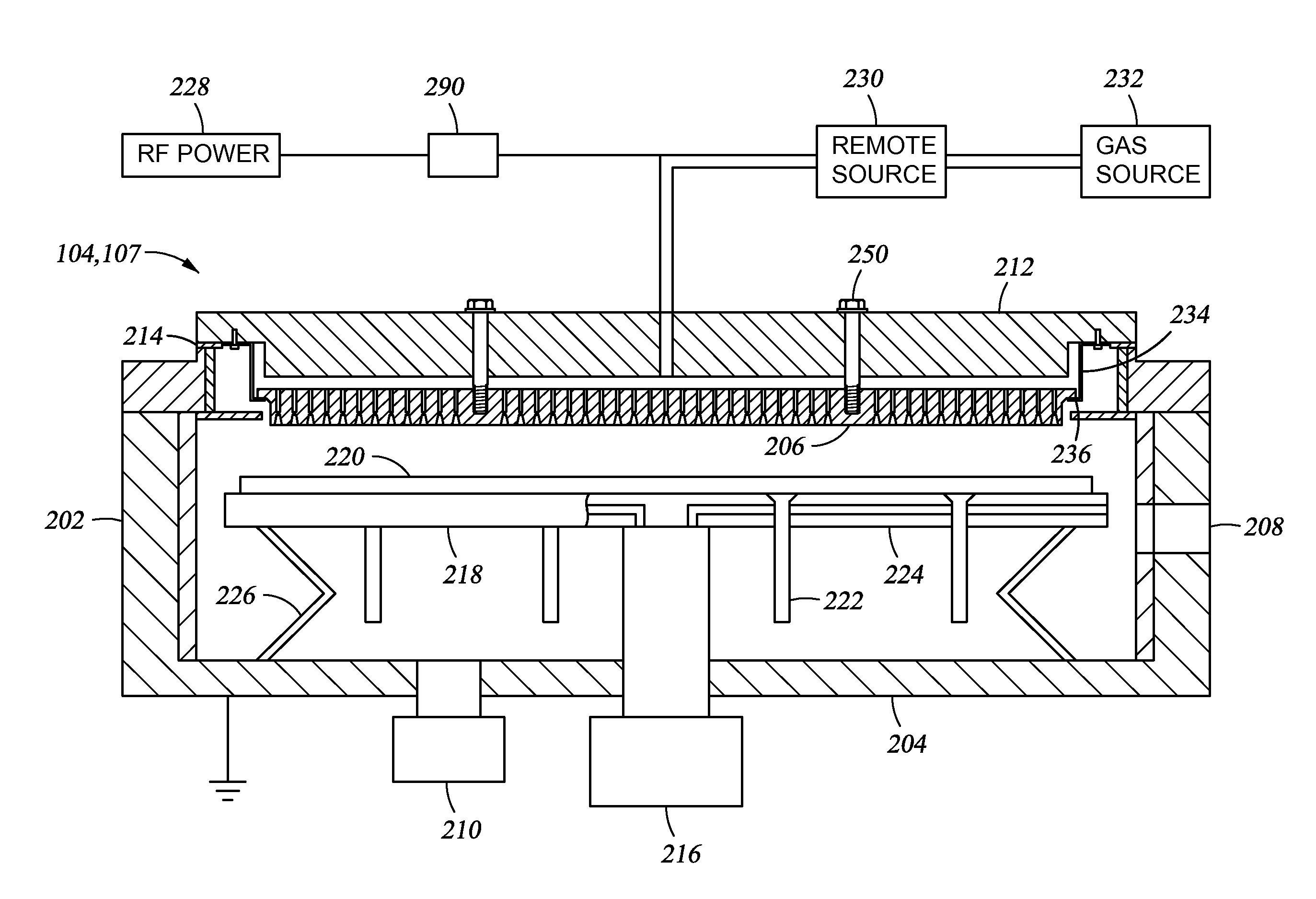
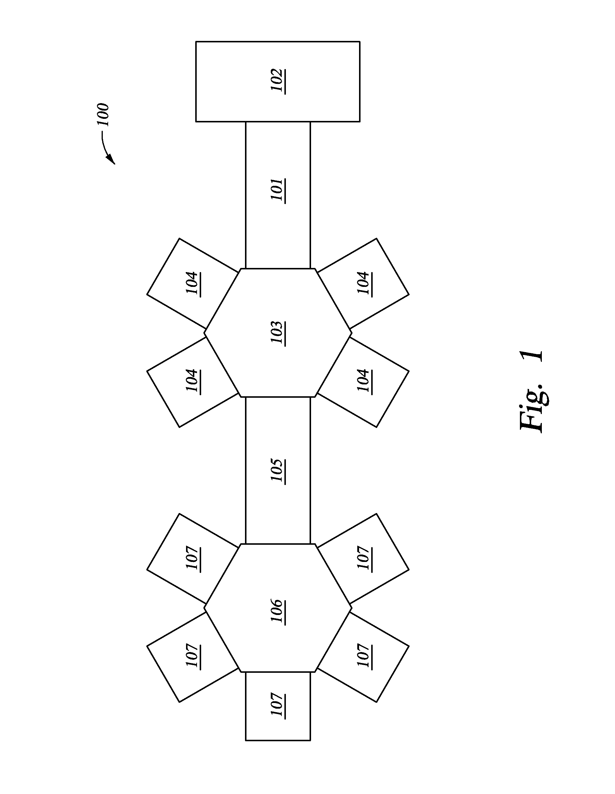
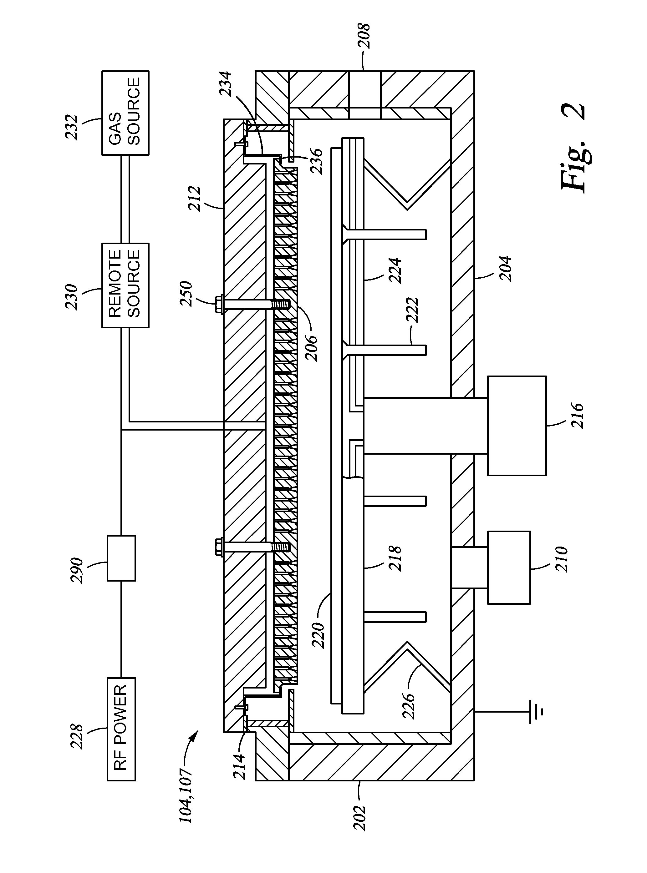
[0019]The present invention generally provides a load lock chamber having slit valve doors. The load lock chamber is used to connect a transfer chamber to a factory interface, or to connect two transfer chambers. When the load lock chamber is between adjacent transfer chambers, the load lock chamber has slit valve doors within the load lock chamber which seal against an inside surface of the load lock chamber. The load lock can thus be serviced at atmospheric pressure without breaking vacuum in the transfer chambers because the atmospheric pressure presses the doors against the inside surface. When the load lock chamber is between a transfer chamber and a factory interface, one slit valve door is disposed outside of the load lock chamber and seals against an outside surface of the load lock chamber. The atmospheric pressure from the factory interface side helps press the door against the outside surface.

[0020]The invention is illustratively described below utilized in a processing s...


PUM

PropertyMeasurementUnit
Pressureaaaaaaaaaa

Abstract

The present invention generally provides a load lock chamber having slit valve doors. The load lock chamber is used to connect a transfer chamber to a factory interface, or to connect two transfer chambers. When the load lock chamber is between adjacent transfer chambers, the load lock chamber has slit valve doors within the load lock chamber which seal against an inside surface of the load lock chamber. The load lock can thus be serviced at atmospheric pressure without breaking vacuum in the transfer chambers because the atmospheric pressure presses the doors against the inside surface. When the load lock chamber is between a transfer chamber and a factory interface, one slit valve door is disposed outside of the load lock chamber and seals against an outside surface of the load lock chamber. The atmospheric pressure from the factory interface side helps press the door against the outside surface.

Description

CROSS-REFERENCE TO RELATED APPLICATIONS[0001]This application claims benefit of U.S. Provisional Patent Application Ser. No. 61 / 698,420, filed Sep. 7, 2012, which is herein incorporated by reference.BACKGROUND OF THE INVENTION[0002]1. Field of the Invention[0003]Embodiments disclosed herein generally relate to a slit valve door for sealing an opening in a load lock chamber.[0004]2. Description of the Related Art[0005]Substrate throughput in semiconductor processing is always a challenge. If technology is to advance, semiconductor substrates continually need to be processed efficiently. Cluster tools have developed as an effective means for processing multiple substrates simultaneously without breaking vacuum. Instead of processing a single substrate and then exposing the substrate to atmosphere during transfer to another chamber, multiple process chambers can be connected to a common transfer chamber so that when a process is complete on the substrate in one process chamber, the sub...

Claims


Application Information

Patent Timeline
IPC IPC(8): C23C16/52
CPCC23C16/52C23C16/54H01J37/32899H01J37/32889H01L21/67126H01L21/67184H01L21/67201H01L21/6719H01L21/67772Y10S414/139
Inventor KURITA, SHINICHI
Owner APPLIED MATERIALS INC
Learn More