Locating Ring and Method for Positioning Parts

a technology of positioning rings and parts, which is applied in the field of positioning rings, can solve the problems of significant negative impact on the productivity of molding operations, significant mold machine downtime, and damage to mold tools or platens that can be very costly

Active Publication Date: 2014-03-20
CERNILIA ANTHONY
View PDF2 Cites 4 Cited by
  • Summary
  • Abstract
  • Description
  • Claims
  • Application Information

AI Technical Summary

Problems solved by technology

It is well known in the injection molding industry that damage to the mold tools or platens can be very costly and have a significant negative impact on productivity of a molding operation.
Substantial mold machine downtime occurs when a machine platen or mold surface must be repaired.
Additionally, significant expense is incurred when necessary to repair the surfaces of a mold tool or platen.
Problems occur when mold tool parts are misaligned and the machine attempts to clamp the mold parts.
However, because the mold components are extremely heavy, bulky and quite large, the operator most times cannot see or adequately determine when proper alignment has occurred.
An operator typically makes several failed attempts to align the locating ring and locating hole.
Each attempt can, and often does, result in varying degrees of damage to the locating ring, machine platen, and locating hole.
If the locating ring is not properly aligned with the locating hole, the locating ring can become damaged, rendering it unsuitable for future use.
If a damaged locating ring were used again instead of repairing or replacing the ring, damage to the locating hole can occur or the ring may not fit properly in the locating hole.
The surfaces of the stationary platen can also become damaged by contact with a damaged locating ring.
When such damage occurs, the mold or platen surface must be immediately repaired, which can be an extremely time-consuming and costly process.
Reworking of the platen or mold can affect the strength and integrity of the structure.
Reworking of the mold part surface can weaken the structure as well.
Many of these surfaces interlock and have essentially no clearance between them.
Any non parallel interfacing between these surfaces can and often will cause premature wear of the communicating surfaces, fracture and thus catastrophic damage of mold parts, and also time and raw material waste producing what are believed-to-be finished parts that ultimately do not specifically meet the product specifications.
However, use of the steel locating ring results in damage to the ring or the platen surface when setting up the mold in the molding machine, and particularly during the positioning process, as noted above.
Non-metal locating rings are typically formed from materials that are inferior when it comes to achieving extremely tight tolerances and size.
Also, locating rings formed of non-metal materials have proven to be unsuitable when it comes to durability.
Such locating rings typically must be replaced much too often.
The non-metal rings are limited to use on cold runner mold tools.
The non-metal locating rings can even become easily damaged when the mold is stored and not being used, simply by coming into contact with other objects.

Method used


Image

  • Locating Ring and Method for Positioning Parts
  • Locating Ring and Method for Positioning Parts
  • Locating Ring and Method for Positioning Parts

Examples


Embodiment Construction

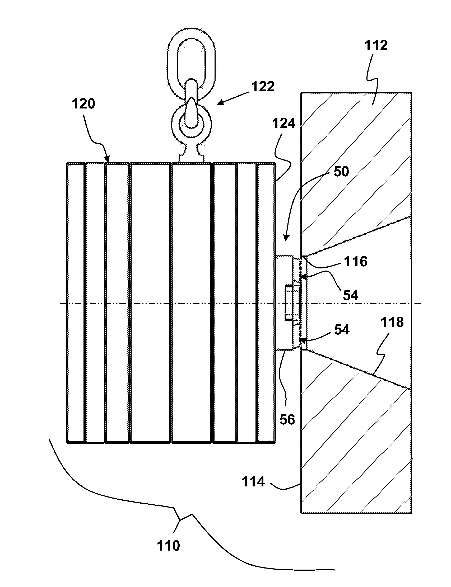
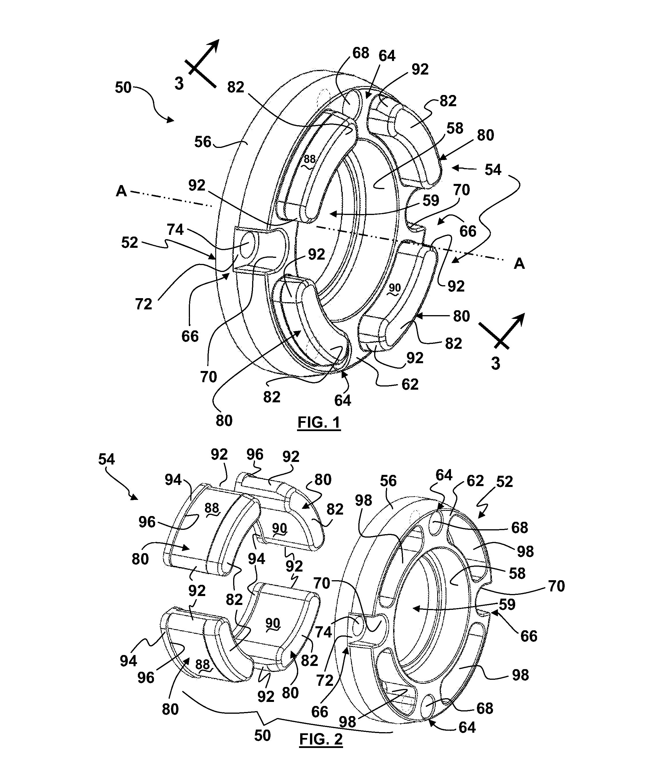
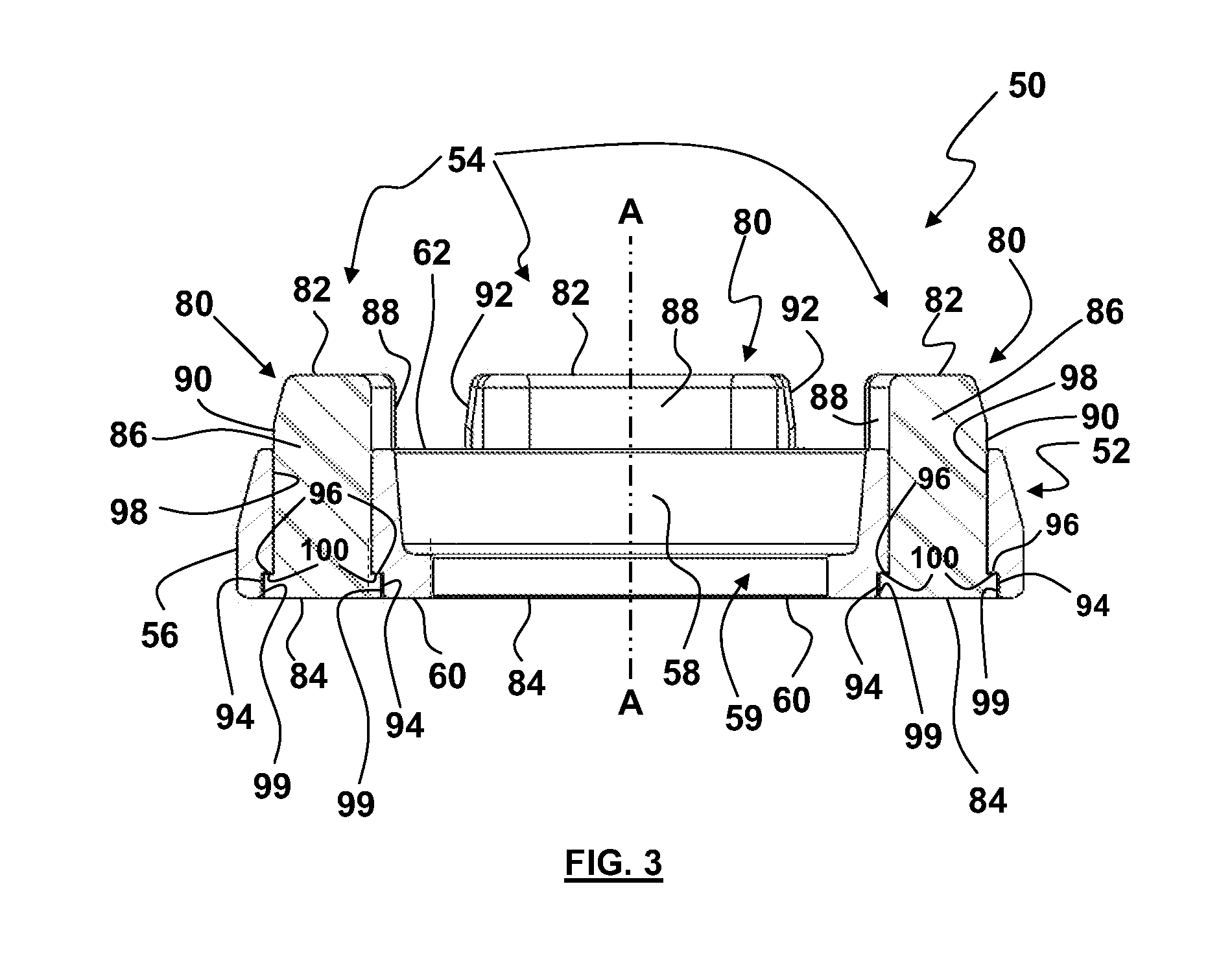
[0081]A locating ring and a method of locating mold tools are disclosed and described herein. The disclosed locating ring and method solve or improve upon one or more of the above-noted and / or other problems and disadvantages with prior known locating rings and methods. In one example, a locating ring has a body formed of a metal material for achieving tight tolerance control, flatness against a mold surface, and durability. The disclosed locating ring also has a somewhat or relatively resilient guard protruding from one face of the body. The disclosed guard can be formed from a non-metal material, a non-ferrous material, or another suitable material and is positioned so as to come in contact with a mold part or other part during locating or positioning of the mold part or other part with another mold part or other part in a mold machine or other machine or equipment. Only when the locating ring is aligned with the locating hole in the other part will the metal portion of the body s...


PUM

PropertyMeasurementUnit
temperatureaaaaaaaaaa
semi-transparentaaaaaaaaaa
transparentaaaaaaaaaa

Abstract

A locating ring has a metal body with a ring shape and having a perimeter surface facing radially outward, a center axis defined by the body, a mounting face, and a locating face spaced from and facing opposite the mounting face along the axis. The locating ring has a guard connected to the body and made of a material that is softer than the metal body. The guard is sized to be radially within the perimeter wall and to project axially beyond the locating face.

Description

RELATED APPLICATION DATA [0001]This application claims priority benefit of, and is filed as a continuation-in-part of, international application no. PCT / 2012 / 0039086 filed on May 23, 2012 and entitled “Locating Ring and Method of Positioning Parts,” which claimed priority benefit of U.S. Provisional Application Ser. No. 61 / 489,177 filed on May 23, 2011 and entitled “Locating Ring and Method for Positioning Parts.” The entire content of each of these prior filed applications is hereby incorporated by reference herein.BACKGROUND [0002]1. Field of the Disclosure[0003]The present invention is generally directed to positioning parts in manufacturing machines, equipment, tools, and the like, and more particularly to a locating ring and locating method for positioning such parts relative to one another.[0004]2. Description of Related Art[0005]It is well known in the injection molding industry that damage to the mold tools or platens can be very costly and have a significant negative impact...

Claims


Application Information

Patent Timeline
Patent Type & Authority Applications(United States)
IPC IPC(8): B29C45/17
CPCB29C45/1742B29C45/1761B29C45/1781F16B19/02Y10T29/4973Y10T29/49895Y10T29/49826B29C33/303B29C45/1743B29C33/74B29C45/04B29C45/1775B29C2045/1776
Inventor CERNIGLIA, ANTHONY
Owner CERNILIA ANTHONY
Why Eureka
Try Eureka