Hydroponic growing system

a growing system and hydroponic technology, applied in the field of hydroponic growing systems, can solve the problems of suffocating the roots of plants, clogging of water lines, loss of mediums, etc., and achieve the effect of minimizing water resistance and minimizing the eroding of mediums

Inactive Publication Date: 2014-03-20
DEGRAFF BRAD
View PDF16 Cites 27 Cited by
  • Summary
  • Abstract
  • Description
  • Claims
  • Application Information

AI Technical Summary

Benefits of technology

[0012]The present invention proposes a new hydroponic growing system that incorporates a soft-sided fabric container made of non-woven material that is housed and/or supported within a plant reservoir container. The system in this invention includes a main reservoir that is in communication with a number of plant reservoirs. Through the function of filtering of the medium by the characteristics of the permeable non-woven material that does not have “drainage holes,” this invention minimizes the medium from eroding and travelling with nutrients when the pump is activated to draw the fluid from the plant reservoir containers and to the main reservoir. By providing a support and/or suspension system

Problems solved by technology

Despite the numerous benefits of the currently available ebb and flow type hydroponic system, each of them is plagued by the medium within the containers and the medium often passes through the holes at the bottom of the container.
This results in the loss of the mediums, and this often causes the water lines to become clogged.
Currently existing hydroponic systems comprise a plastic “bucket within a bucket” when used as the top pot, and this is a major problem as the fabric container is not rigid enough to rest on top plant container reservoirs as they do with pre-existing systems.
This is also problematic since the fabric container would be resting in the remaining liquid nutrients

Method used


Image

  • Hydroponic growing system
  • Hydroponic growing system
  • Hydroponic growing system

Examples


Embodiment Construction

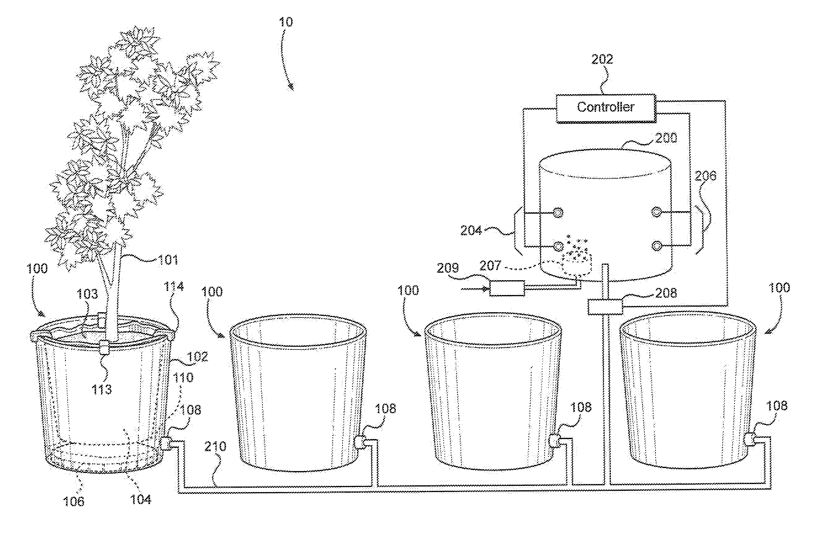
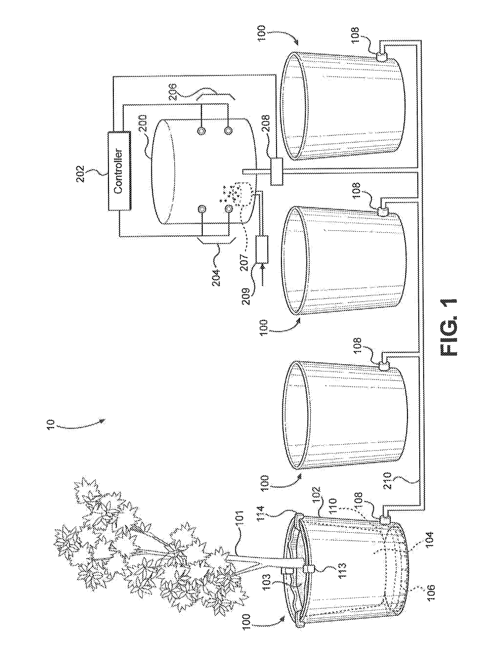
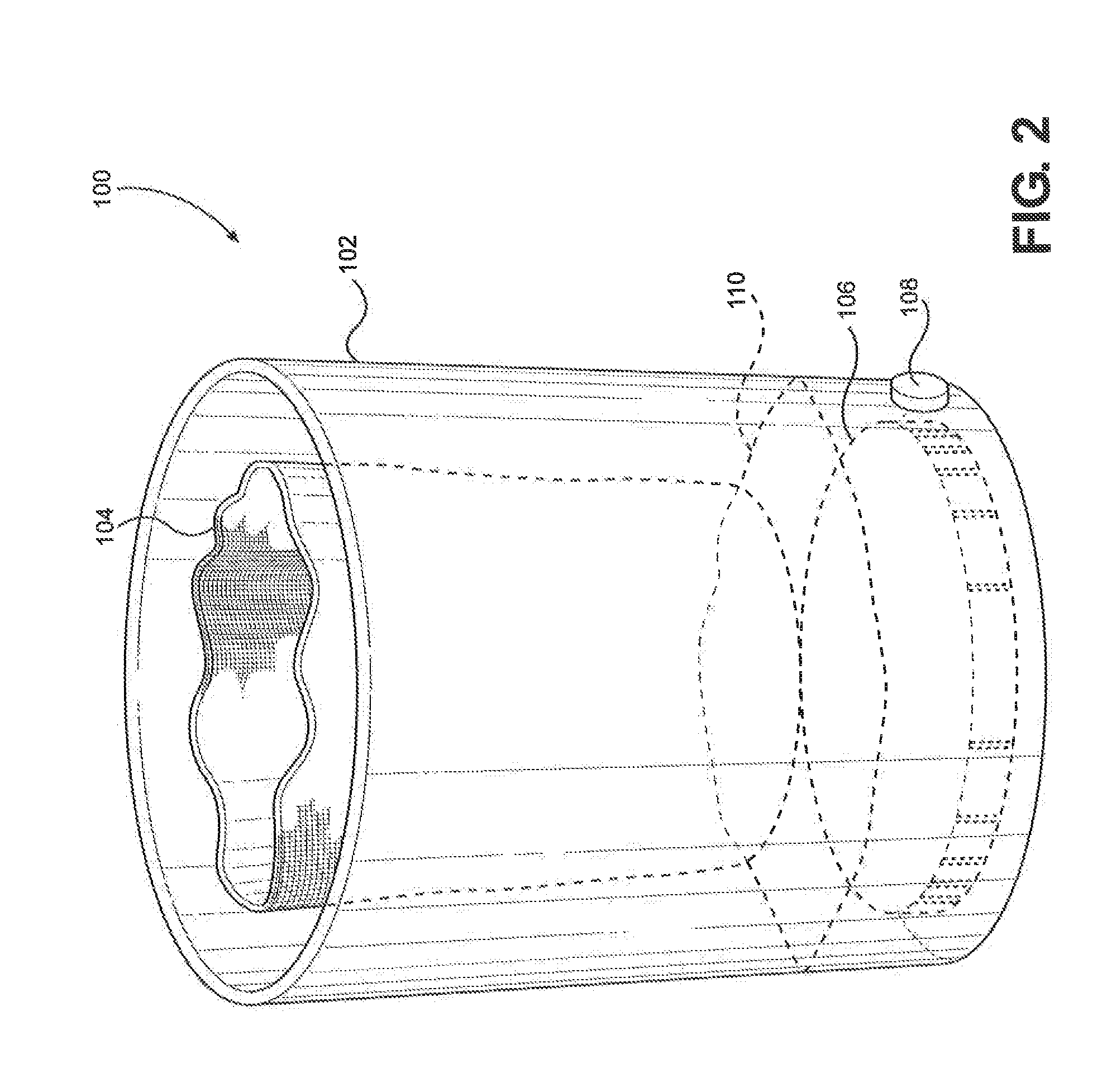
[0029]Referring initially to FIG. 1, a hydroponic growing system in the present invention is generally designated 10, and includes multiple plant reservoir containers 100 and a main reservoir 200 connected to the controller 202 is illustrated. The individual plant reservoir container 100 is connected to the main reservoir 200 and to the other plant reservoir containers 100 through the connection port 108 on each plant reservoir container 100 and the connection pipeline 210. The connection ports 108 are used both for the inlet and outlet of the fluid from the main reservoir 200 to the plant reservoir containers 100. According to predetermined intervals controlled by a float and timing mechanism set up by the controller 202, the “fill” switches 204 are activated through the pump 208 and thus, the plant reservoir containers 100 are flooded to a specific water level 110 to immerse the soft-sided fabric container 104 to supply water and other nutrients to the roots of the plant 101. Foll...


PUM


Abstract

A new hydroponic growing system that incorporates a non-woven soft-sided fabric container housed and/or supported within a plant reservoir container is proposed. The present invention includes a main reservoir that is in communication with multiple plant reservoir containers connected each other. The predetermined intervals are set and controlled by the controller at the main reservoir to fill and drain the plant reservoir containers. With an aid of use of a soft-sided fabric container made of fine mesh-like non-woven material, the present invention minimizes the medium from travelling with nutrients when the pump is activated to drain the bucket. In addition, the present invention includes aeration devices, such as an air tube, creating a vent which minimizes water resistance when draining the bucket. Variations on the type or material for the soft-sided fabric container, and various methods for supporting and suspending the soft-sided fabric containers can be considered.

Description

RELATED APPLICATION[0001]This application claims the benefit of priority to U.S. Provisional Patent Application Ser. No. 61 / 536,490, entitled “Hydroponic Growing System” filed on Sep. 19, 2011, and currently co-pending.FIELD OF THE INVENTION[0002]The present invention pertains generally to devices for a hydroponic growing system for plants. The present invention is more particularly, though not exclusively, useful as adopting a soft-sided fabric container made of non-woven material that is housed and / or supported within a plant reservoir container in a hydroponic growing system. By adopting a non-woven material, the present invention minimizes the soil erosion or medium loss generally developed from travelling with liquid nutrients when the pump is activated to draw the fluid between plant reservoir containers and a main reservoir.BACKGROUND OF THE INVENTION[0003]Hydroponics is a method of growing plants using mineral nutrient solutions in water, without an aid of soil. Terrestrial ...

Claims


Application Information

Patent Timeline
IPC IPC(8): A01G31/02
CPCA01G31/02A01G27/005Y02P60/21
Inventor DEGRAFF, BRAD
Owner DEGRAFF BRAD
Why Eureka
Try Eureka