Eureka AIR delivers breakthrough ideas for toughest innovation challenges, trusted by R&D personnel around the world.

Image forming apparatus, method for controlling image forming apparatus, and computer-readable recording medium

a technology of image forming apparatus and control method, which is applied in the direction of instruments, computing, electric digital data processing, etc., can solve the problems of troublesome user operation of specifying the target display area, difficult to get an overview of all of a large number of function buttons, and difficulty in displaying all function buttons corresponding to all functions on the operation panel unit. achieve the effect of improving user's operability of setting screen

Inactive Publication Date: 2014-03-20
KONICA MINOLTA INC
View PDF9 Cites 5 Cited by
  • Summary
  • Abstract
  • Description
  • Claims
  • Application Information

AI Technical Summary

Benefits of technology

The present invention aims to enhance the ease of use of the settings screens on an image forming apparatus.

Problems solved by technology

For this reason, it is difficult to display all function buttons corresponding to all functions on the operation panel unit (display unit) of an image forming apparatus.
With such a tab screen switching technique, however, a plurality of function buttons that span different function groups are presented in different tab screens, and thus it is difficult to get an overview of all of a large number of function buttons.
Thus, the operation of specifying the target display area, which involves the movement of the slider, may be troublesome for a user who has already decided which function to set.

Method used


Image

  • Image forming apparatus, method for controlling image forming apparatus, and computer-readable recording medium
  • Image forming apparatus, method for controlling image forming apparatus, and computer-readable recording medium
  • Image forming apparatus, method for controlling image forming apparatus, and computer-readable recording medium

Examples


Embodiment Construction

[0034]Hereinafter, an embodiment of the present invention will be described with reference to the drawings.

1. Configuration

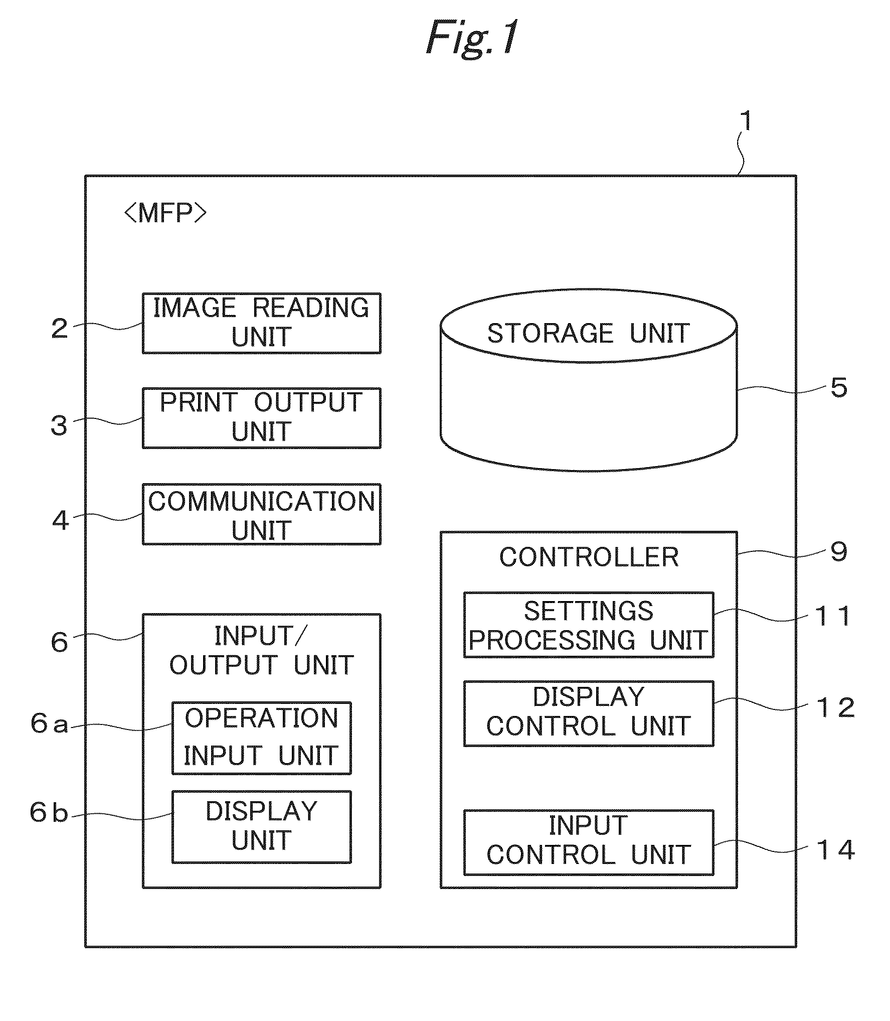
[0035]FIG. 1 is a functional block diagram showing a configuration of an image forming apparatus 1. In the present embodiment, the image forming apparatus 1 is configured as a Multi-Function Peripheral (also referred to simply as an “MFP”). The MFP is an apparatus (also referred to as a “Multi-Functional Peripheral”) having various functions such as a scan function, a print function, a copy function, and a facsimile function.

[0036]As illustrated in FIG. 1, the image forming apparatus 1 includes, for example, an image reading unit 2, a print output unit 3, a communication unit 4, a storage unit 5, an input / output unit 6, and a controller 9, and implements various functions by operating these units in combination.

[0037]The image reading unit 2 is a processing unit configured to optically read an original document placed at a predetermined position on the image for...


PUM


Abstract

A setting screen displayed on a display unit of an image forming apparatus includes an icon display area displaying a plurality of icons that are arranged in a predetermined direction and correspond to a plurality of function buttons for setting each function, and a function button display area displaying one or more of the plurality of function buttons. An input control unit of the image forming apparatus receives input of a group display instruction to display function buttons that belong to one of a plurality of groups in the function button display area. A display control unit of the image forming apparatus displays, in response to the input of the group display instruction, function buttons that belong to a specific group specified by the input of the group display instruction in the function button display area.

Description

[0001]This application is based on Japanese Patent Application No. 2012-205579 filed on Sep. 19, 2012, the contents of which are hereby incorporated by reference.BACKGROUND OF THE INVENTION[0002]1. Technical Field[0003]The present invention relates to an image forming apparatus and a technique related thereto.[0004]2. Related Art[0005]As image forming apparatuses take on more and more functions year after year, the number of buttons (function buttons) for setting the functions of an image forming apparatus is also increasing. For this reason, it is difficult to display all function buttons corresponding to all functions on the operation panel unit (display unit) of an image forming apparatus.[0006]Meanwhile, there is a technique for classifying a large number of function buttons into a plurality of function groups and switching among and displaying a plurality of tab screens (tab screens for the respective function groups), each including function buttons that belong to each functio...

Claims


Application Information

Patent Timeline
Patent Type & Authority Applications(United States)
IPC IPC(8): G06F3/0481
CPCG06F3/04817H04N1/00411H04N1/00413H04N1/00437H04N1/00474H04N1/00482H04N2201/0094
Inventor OKADA, TAKUYAKURUMASA, YOICHIHOSONO, MASAOKOMABA, KENICHITOMIYASU, KAZUHIRO
Owner KONICA MINOLTA INC
Why Eureka
Eureka Blog
Learn More