Eureka AIR delivers breakthrough ideas for toughest innovation challenges, trusted by R&D personnel around the world.

External device control method, imaging device control method, imaging system control method, external device, imaging device, and imaging system

Active Publication Date: 2016-05-26
CANON KK
View PDF24 Cites 4 Cited by
  • Summary
  • Abstract
  • Description
  • Claims
  • Application Information

AI Technical Summary

Benefits of technology

The present invention provides a way for users to easily determine if they can use a camera's preset tour operation without causing a random operation. This improves the user's ability to operate the camera. Additionally, the invention provides external devices and imaging devices that allow for easier use of the camera's preset tour operation.

Problems solved by technology

In the latter case, there is a problem that it is difficult for a user to externally determine whether or not a target surveillance camera is capable of performing a random operation.
Such operations are complicated.

Method used


Image

  • External device control method, imaging device control method, imaging system control method, external device, imaging device, and imaging system
  • External device control method, imaging device control method, imaging system control method, external device, imaging device, and imaging system
  • External device control method, imaging device control method, imaging system control method, external device, imaging device, and imaging system

Examples


first embodiment

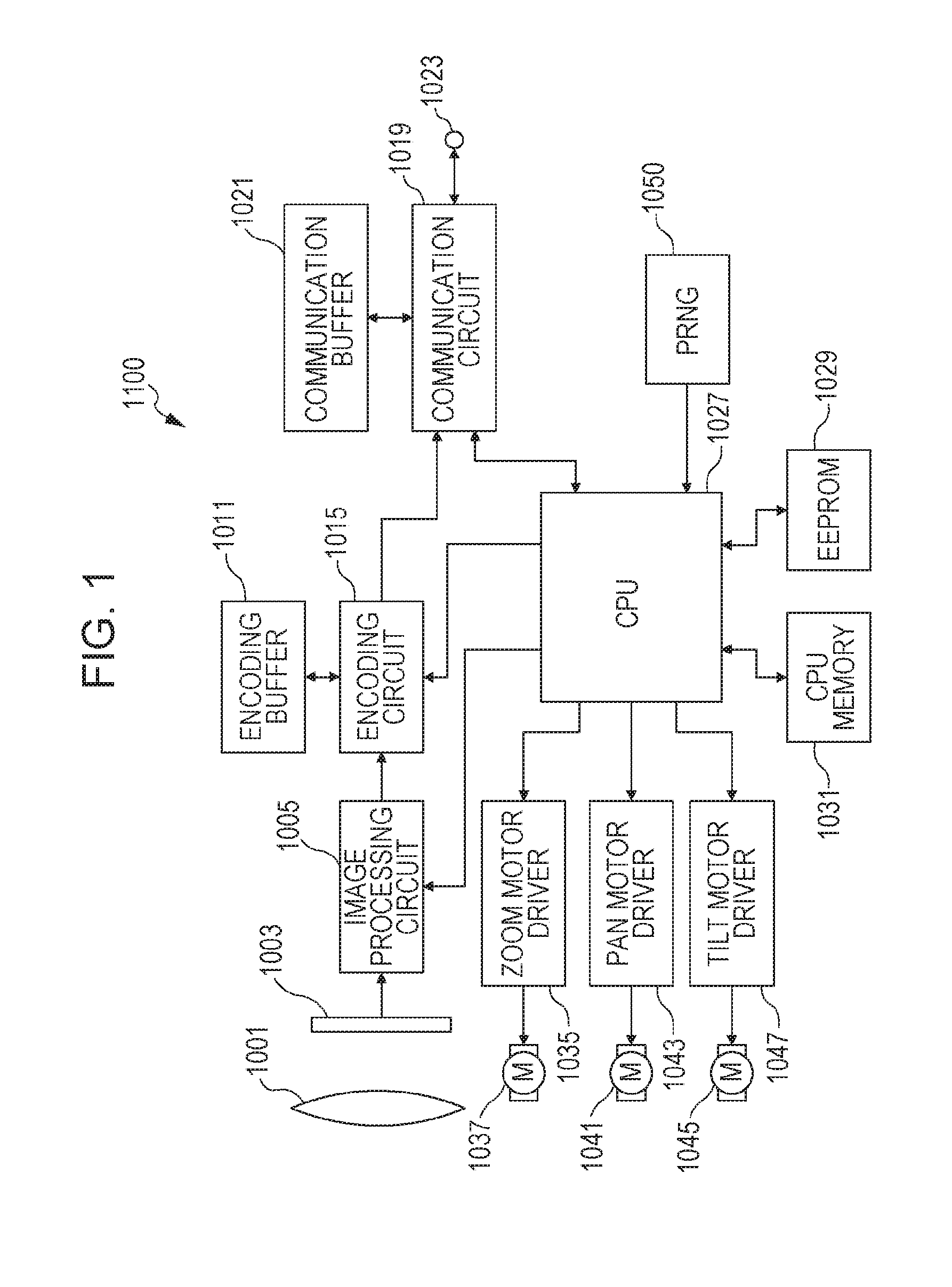
[0057]FIG. 1 is a block diagram illustrating a configuration of a surveillance camera 1100 as an imaging device according to a first embodiment. Referring to FIG. 1, reference numeral 1001 denotes an imaging optical system, reference numeral 1003 denotes an imaging element, and reference numeral 1005 denotes an image processing circuit. Further, reference numeral 1011 denotes an encoding buffer, reference numeral 1015 denotes an encoding circuit, reference numeral 1019 denotes a communication circuit (hereinafter, may be referred to as an interface (IF) circuit), reference numeral 1021 denotes a communication buffer, and reference numeral 1023 denotes a communication port.

[0058]Reference numeral 1027 denotes a central arithmetic processing unit (hereinafter, may be referred to as a CPU), reference numeral 1029 denotes an electrically erasable, programmable read-only memory (hereinafter, may be referred to as an EEPROM), and reference numeral 1031 denotes a CPU memory.

[0059]Reference...

second embodiment

[0304]FIGS. 12A to 12C illustrate a configuration example of a PTZPresetTourStartingConditionExtension type according to a second embodiment. The same elements as those in the first embodiment will be referred to with the same signs as those in the first embodiment, and explanation of those same elements will be omitted.

[0305]FIG. 12A illustrates a configuration example of a PTZPresetTourStartingConditionExtension type. Referring to FIG. 12A, the first field of the PTZPresetTourStartingConditionExtension type is an ExtendedRecurringDuration field. This field is described as a PTZPresetTourRecurringDurationExtended type.

[0306]Further, the next field of the PTZPresetTourStartingConditionExtension type is an ExtendedDirection field. This field is described as a PTZPresetTourDirectionExtended type.

[0307]In the second embodiment, the last field of the PTZPresetTourStartingConditionExtension type is an Extension field. This field is a field reserved for future extension.

[0308]FIG. 12B ill...

third embodiment

[0318]FIGS. 13A and 13B illustrate a configuration example of a PTZPresetTourStartingCondition type according to a third embodiment. The same elements as those in the foregoing embodiments will be referred to with the same signs as those in the foregoing embodiments, and explanation of those same elements will be omitted.

[0319]In the PTZPresetTourStartingCondition type illustrated in FIGS. 13A and 13B, the capability of the surveillance camera 1100 according to the third embodiment for a random operation regarding a preset tour is described with an attribute element of this type.

[0320]FIG. 13A illustrates a configuration example in the case where an XML pre-defined string type is used for the attribute element.

[0321]In the configuration example of the PTZPresetTourStartingCondition type illustrated in FIG. 13A, the first attribute is ExtendedRecurringDuration. This attribute is used for issuing an instruction to determine the standby time between a tour and the next tour in a random...


PUM


Abstract

A determination as to whether or not a random operation is able to be performed for a preset tour of a surveillance camera may be easily made, and user's operability may be improved. A client device transmits a command for making an inquiry about the capability of the surveillance camera for a random operation regarding a preset tour. The surveillance camera receives the command, and transmits capability information of the random operation to the client device. The client device analyzes the received information, and changes the GUI display of the client device.

Description

TECHNICAL FIELD[0001]The present invention relates to an external device control method, an imaging device control method, an imaging system control method, an external device, an imaging device, and an imaging system, and more particularly, is suitably used for a case where an imaging unit is caused to perform a tour operation to capture images.BACKGROUND ART[0002]A function of surveillance cameras has been known which performs a so-called “preset tour”, in which surveillance is carried out by performing a tour operation of a plurality of photographing points. Furthermore, a surveillance system has been known in which an external surveillance control device generates, in a random manner, the photographing order of photographing points, the moving speeds of movement between the photographing points, photographing times at the photographing points, or the like for the preset tour.[0003]A surveillance camera device is disclosed in PTL 1. In the surveillance camera device, a plurality ...

Claims


Application Information

Patent Timeline
IPC IPC(8): H04N7/18H04N5/232H04N5/44
CPCH04N7/183H04N5/23296H04N5/23293H04N5/44H04N7/181G03B17/561G03B37/02G08B13/1963H04N23/66H04N23/661H04N23/63H04N23/695H04N23/69
Inventor NIIDA, MITSUO
Owner CANON KK
Why Eureka
Eureka Blog
Learn More