System and method for an interbody spinal fusion assembly

Active Publication Date: 2014-03-27
KIC VENTURES LLC
View PDF5 Cites 65 Cited by
  • Summary
  • Abstract
  • Description
  • Claims
  • Application Information

AI Technical Summary

Benefits of technology

[0004]The present invention relates to an interbody spinal fusion assembly that includes an interbody cage, planar metal pins and bone fasteners. The interbody cage includes a metal cage and a PEEK insert. The PEEK insert is inserted i

Problems solved by technology

Fibula strut grafts have a proven history of effectiveness for anterior cervical corpectomies but are inherently vulnerable to complications such as early or late fracture, dislodgement, displacement, telescoping into the vertebral body, or nonunion.
However, PEEK cages ten

Method used


Image

  • System and method for an interbody spinal fusion assembly
  • System and method for an interbody spinal fusion assembly
  • System and method for an interbody spinal fusion assembly

Examples


Embodiment Construction

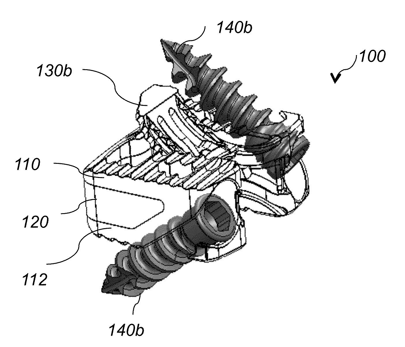
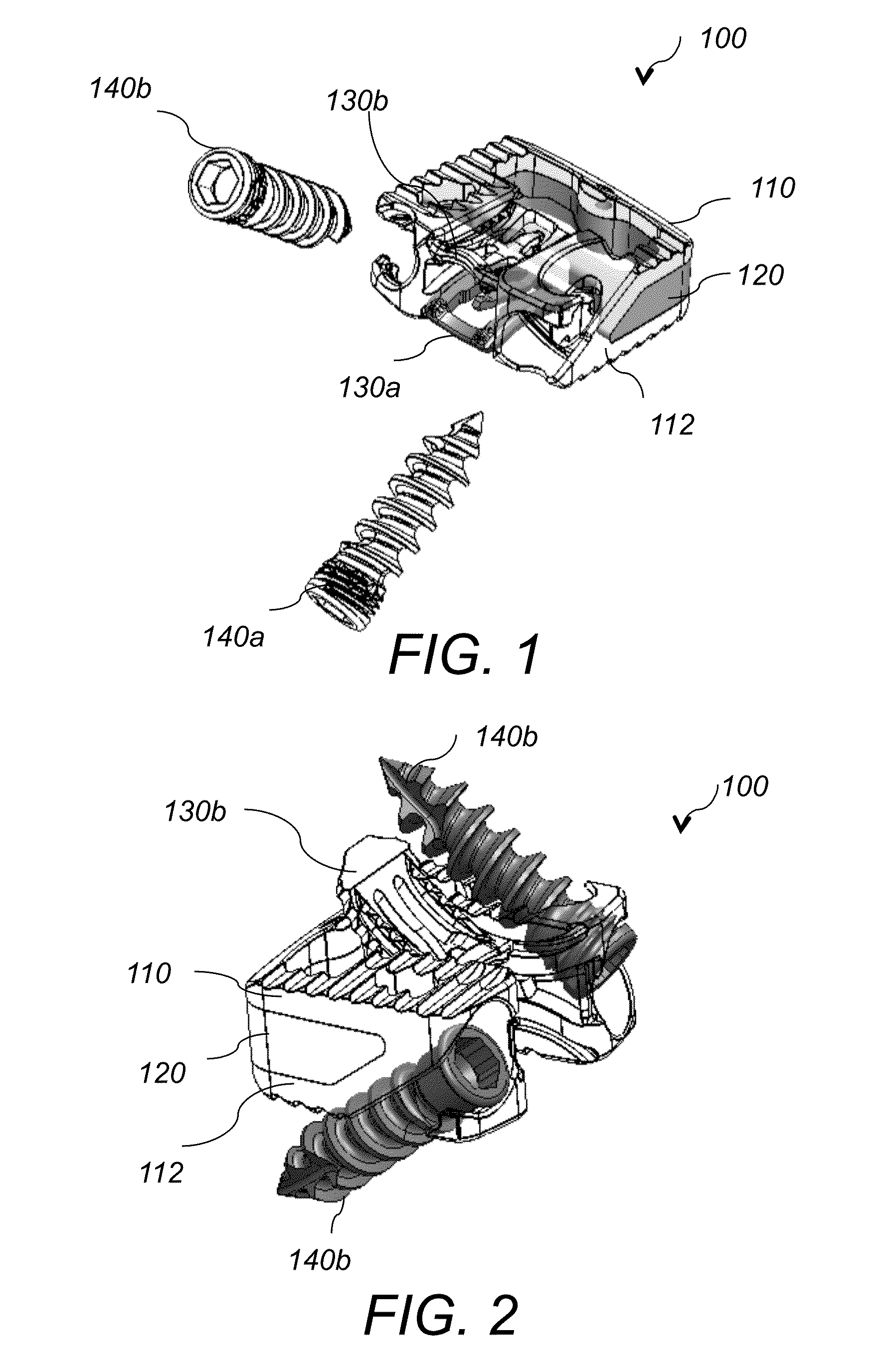
[0065]The present invention relates to an interbody spinal fusion assembly that includes an interbody cage, planar metal pins and bone fasteners. The interbody cage is inserted in the space between two adjacent vertebras and is secured in placed with metal planar pins and bone engaging fasteners.

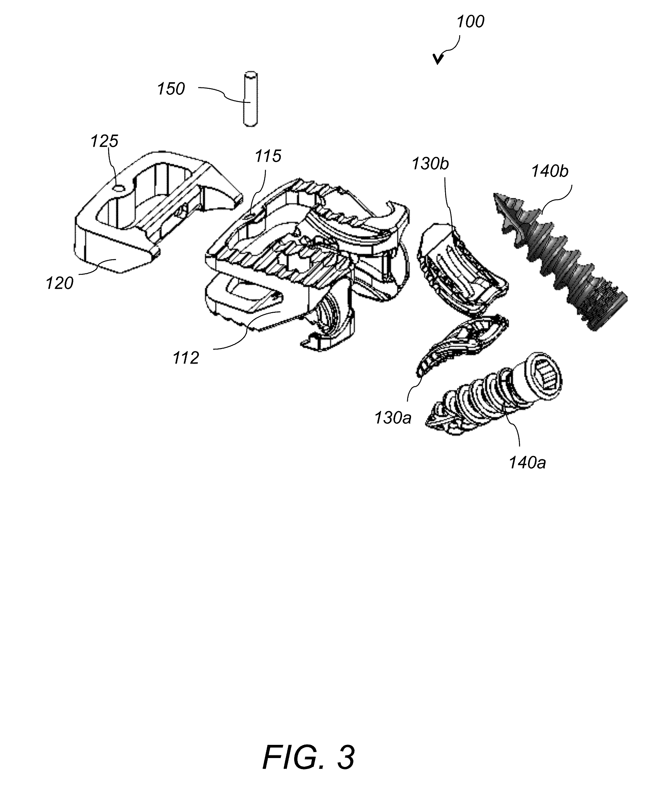
[0066]Referring to FIG. 1, FIG. 2 and FIG. 3, interbody spinal fusion assembly 100 includes an interbody cage 110, planar pins 130a, 130b and bone engaging fasteners 140a, 140b. Interbody cage 110 includes a metal cage 112 and an insert 120. Insert 120 is made of PEEK or other plastic material and is positioned within a slot 114 formed at the front side 112a of the metal cage 112. Metal cage 112 is made of titanium, steel, or any other biocompatible metal or alloy. Insert 120 is secured to the metal cage 112 with a pin 150 positioned within through opening 115 of the metal cage and through opening 125 of the insert. Referring to FIG. 4A-FIG. 4D, metal cage 112 has a slot opening 114 in the f...


PUM


Abstract

An interbody spinal fusion assembly includes an interbody cage, planar metal pins and bone fasteners. The interbody cage includes a metal cage and a PEEK insert. The PEEK insert is inserted into a slot of the metal cage and is secured to the metal cage with a pin. The assembled interbody cage is inserted in the space between two adjacent vertebras and is secured in placed with the planar metal pins and the bone fasteners.

Description

CROSS REFERENCE TO RELATED CO-PENDING APPLICATIONS[0001]This application claims the benefit of U.S. provisional application Ser. No. 61 / 704,800 filed Sep. 24, 2012 and entitled “SYSTEM AND METHOD FOR AN INTERBODY SPINAL FUSION ASSEMBLY”, the contents of which are expressly incorporated herein by reference.FIELD OF THE INVENTION[0002]The present invention relates to a system and a method for an interbody spinal fusion assembly, and more particularly to an interbody spinal fusion assembly that includes an interbody cage, planar metal pins and bone engaging fasteners.BACKGROUND OF THE INVENTION[0003]Fibula strut grafts have a proven history of effectiveness for anterior cervical corpectomies but are inherently vulnerable to complications such as early or late fracture, dislodgement, displacement, telescoping into the vertebral body, or nonunion. The settling and resultant segmental kyphosis after multi-level anterior cervical reconstruction have also been documented. The risk of graft ...

Claims


Application Information

Patent Timeline
IPC IPC(8): A61F2/44A61F2/46
CPCA61F2/4611A61F2/447A61B17/8033A61B17/8052A61F2/30749A61F2/4455A61F2002/30331A61F2002/305A61F2002/30571A61F2002/30578A61F2002/30579A61F2002/30604A61F2002/30733A61F2002/30787A61F2002/30878A61F2002/30884A61F2002/30904A61F2002/4619A61F2002/4627A61F2002/4629
Inventor CHIN, KINGSLEY R.YIN, LINLORE, VITOIBARRA, MATTHEWDRNEK, MICHAEL
Owner KIC VENTURES LLC
Why Eureka
Try Eureka