Cable injector for deploying artificial lift system

a technology of artificial lift system and injector, which is applied in the direction of sealing/packing, drilling pipes, and well accessories, etc., can solve the problems of limited cable deployment in coil tubing, cost, reliability and availability of coiled tubing units, and the inability to use a broader base of cable insertion

Inactive Publication Date: 2014-04-17
ZEITECS
View PDF10 Cites 36 Cited by
  • Summary
  • Abstract
  • Description
  • Claims
  • Application Information

AI Technical Summary

Benefits of technology

The present disclosure relates to a cable injector for deploying an artificial lift system in a wellbore. The injector includes a traction assembly with a stationary segment and a movable segment. The frame is connected to the stationary segment and has a passage for receiving the cable. The injector also includes a motor torsionally connected to the drive sprocket of the stationary segment. The method involves connecting the downhole tool to a cable, lowering the tool into a pressure control assembly and wellhead adjacent to the wellbore, connecting the cable injector to the assembly, and operating the injector to inject the cable into the wellbore and lower the tool to a desired depth. The technical effect of the invention is to provide a reliable and efficient tool for deploying an artificial lift system in a wellbore.

Problems solved by technology

The oil industry has used electric submersible pumps (ESPs) for decades to produce high flow-rate wells. However, the materials and design of these pumps have improved their ability to survive for longer periods of time without intervention. Deploying these systems requires the operator to pull the tubing string and power cable, which requires a well servicing rig and special spooler to spool the cable safely. The industry has been trying to find alternative methods, especially in offshore and remote locations where the cost increases significantly. Limited deployment of cable inserted in coil tubing has been attempted, but it is expensive, unreliable, and not widely available. Therefore, the technical problem of this patent text is finding a cost-effective and reliable alternative to the current deployment method of electric submersible pumps.

Method used


Image

  • Cable injector for deploying artificial lift system
  • Cable injector for deploying artificial lift system
  • Cable injector for deploying artificial lift system

Examples


Embodiment Construction

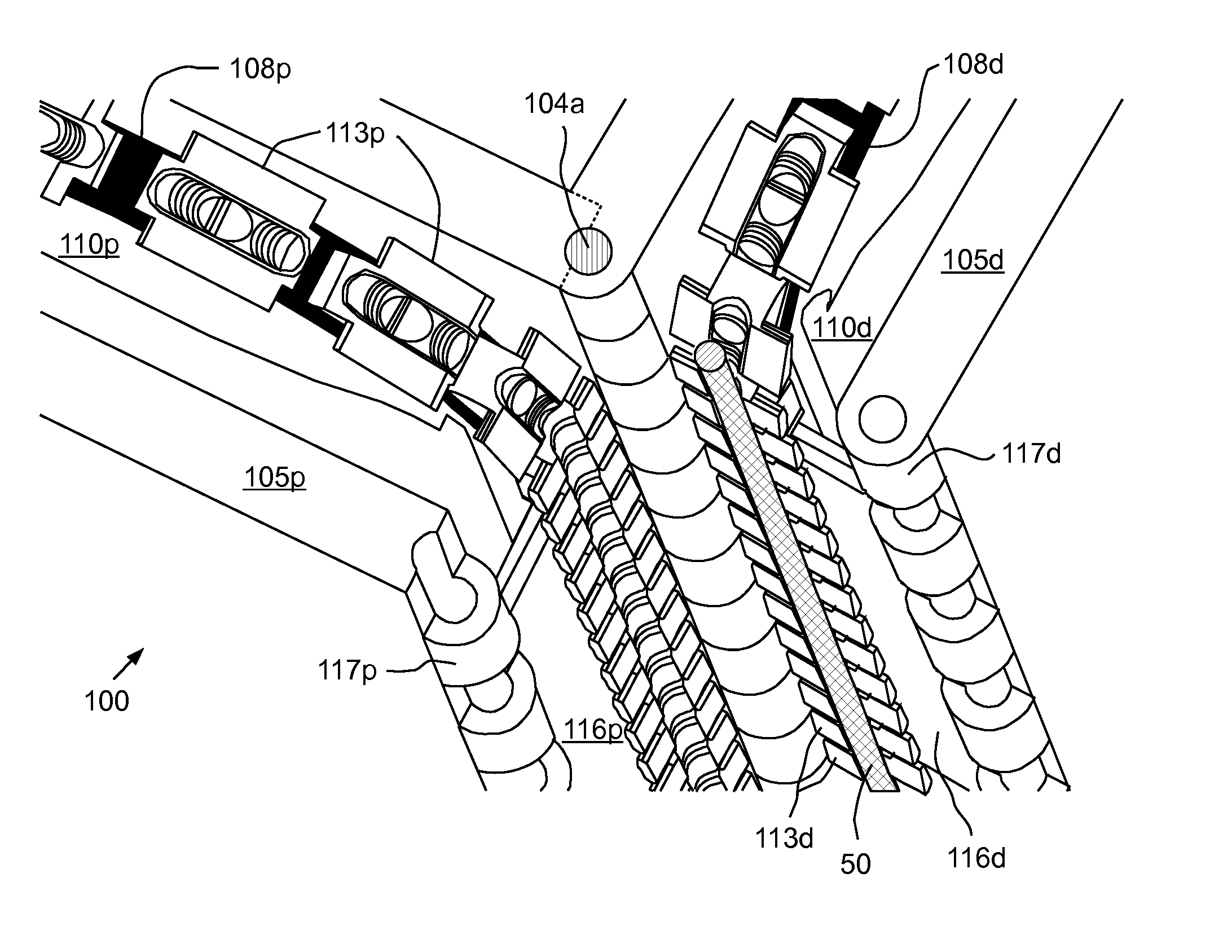
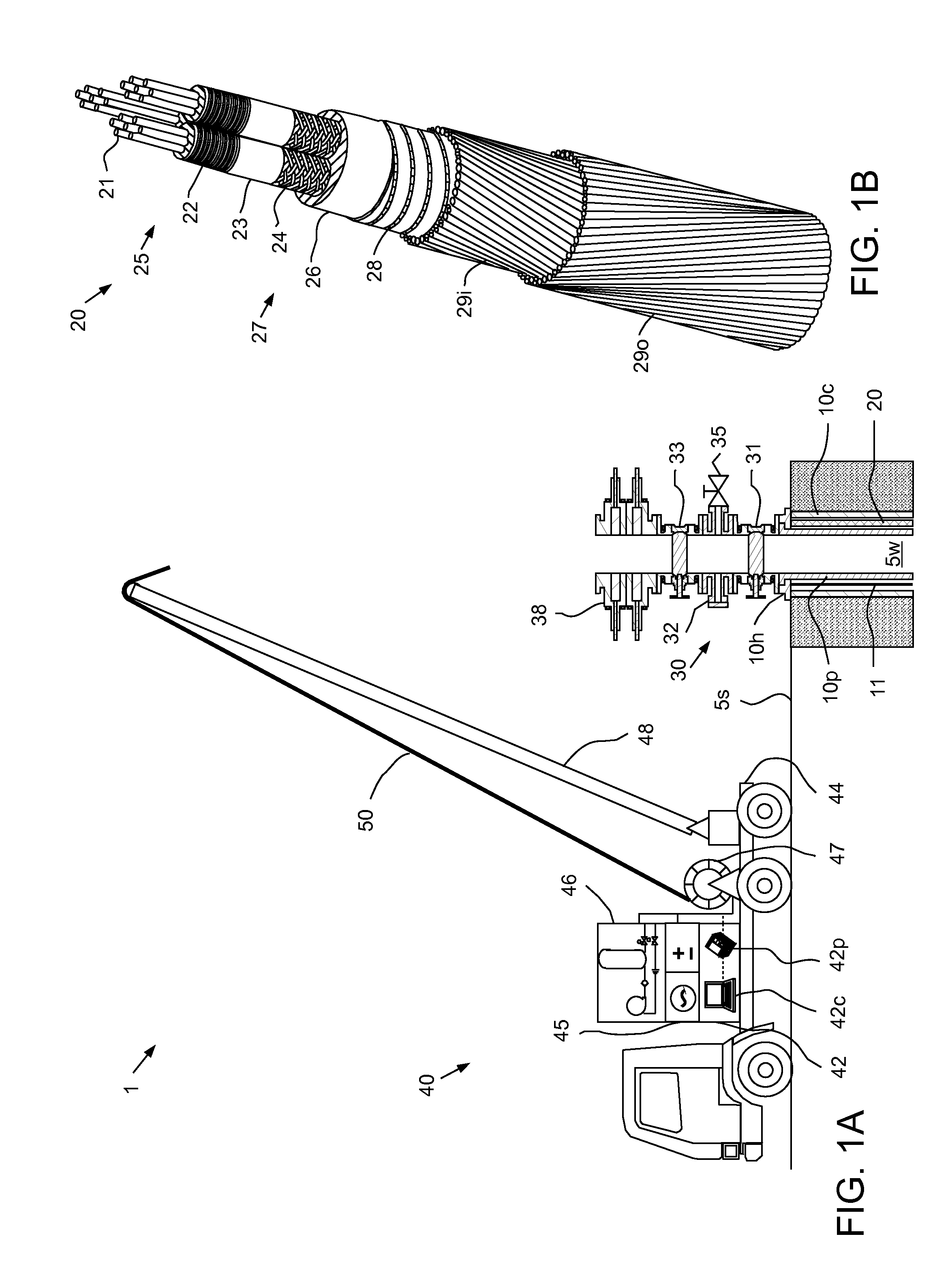
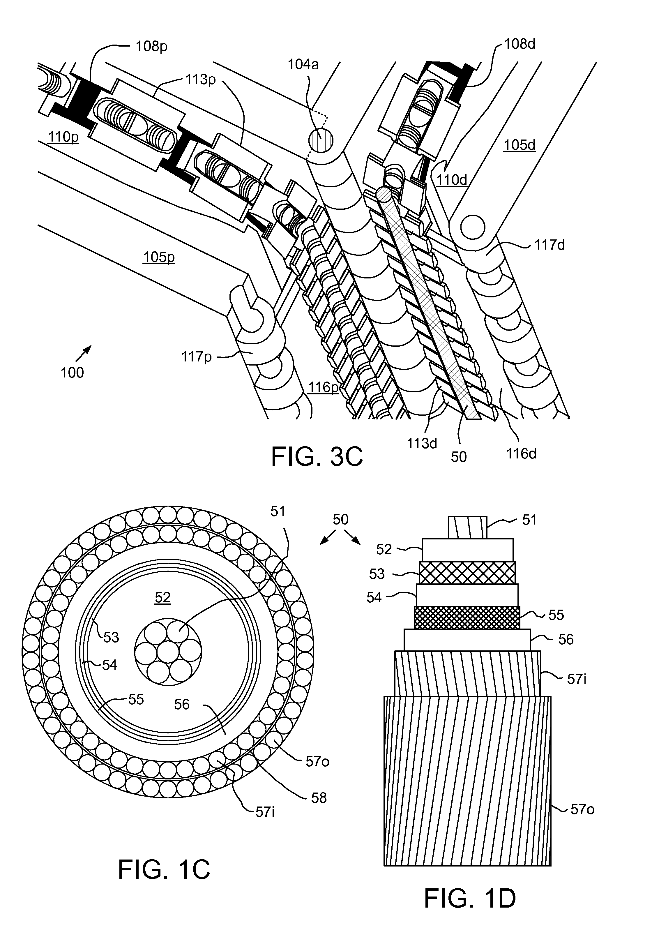
[0016]FIG. 1A illustrates a launch and recovery system (LARS) 1 at a wellsite for deploying an artificial lift system (ALS), according to one embodiment of the present disclosure. The LARS 1 may include a wireleine truck 40, a pressure control assembly (PCA), such as one or more (two shown) blowout preventers (BOPs) 38, one or more running tools 59 (FIG. 4A), and a cable injector 100 (FIG. 3A).

[0017]A wellbore 5w has been drilled from a surface 5s of the earth into a hydrocarbon-bearing (i.e., crude oil and / or natural gas) reservoir 6 (FIG. 4A). A string of casing 10c has been run into the wellbore 5w and set therein with cement (not shown). The casing 10c has been perforated 9 (FIG. 4B) to provide to provide fluid communication between the reservoir 6 and a bore of the casing 10c. A wellhead 10h has been mounted on an end of the casing string 10c. A string of production tubing 10p extends from the wellhead 10h to the reservoir 6 to transport production fluid 7 (FIG. 4C) from the re...


PUM


Abstract

An injector for deploying a cable into a wellbore includes a traction assembly having at least a stationary segment and a movable segment. Each segment includes: a drive sprocket; an idler sprocket; a track looped around and between the sprockets; a set of grippers fastened to and disposed along the respective track, and a frame. The frame: is connected to the stationary segment, has a coupling for connection to a pressure control assembly (PCA), and has a passage for receiving the cable. The injector further includes a motor torsionally connected to the drive sprocket of the stationary segment.

Description


Claims


Application Information

Patent Timeline
Owner ZEITECS
Why Eureka
Try Eureka