
Lubricating oil monitoring and maintenance cap with oil level monitoring system

a technology of oil level monitoring and lubricating oil, which is applied in the direction of mechanical equipment, machines/engines, transportation and packaging, etc., can solve the problems of roller failure, high maintenance cost, and high cost of time-consuming repair

Inactive Publication Date: 2014-05-01
KILE RONALD J
View PDF18 Cites 17 Cited by
  • Summary
  • Abstract
  • Description
  • Claims
  • Application Information

AI Technical Summary

Benefits of technology

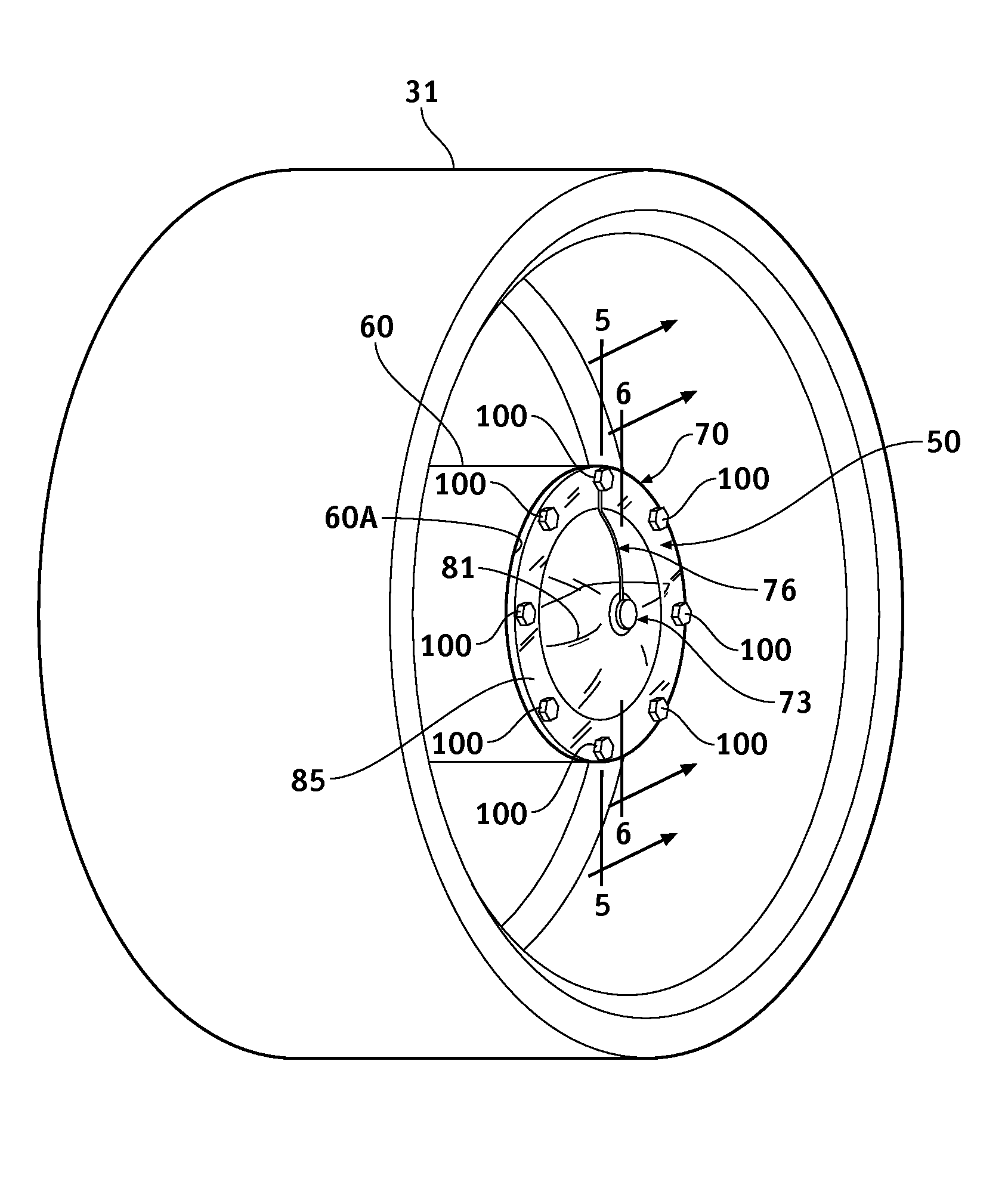
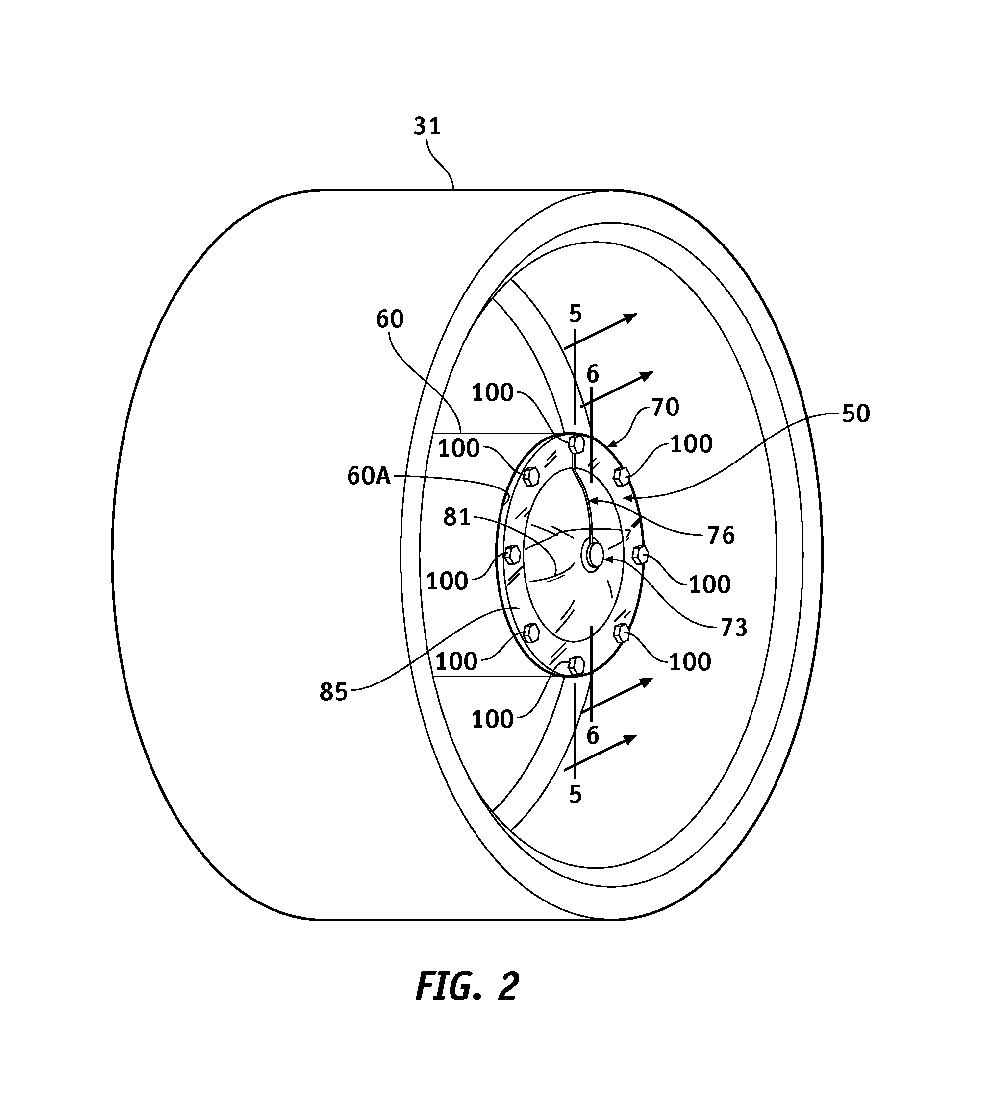
[0004]According to the principle of the invention, an apparatus includes a lubricating oil reservoir with an open end closed by a cap removably coupled to the open end, and the cap has a lubricating oil engaging side that faces the lubricating oil reservoir and a sensor located in the lubricating oil reservoir. The lubricating oil reservoir is for holding a volume of lubricating oil for providing machine lubrication, which said volume of lubricating oil is to extend vertically upward into the lubricating oil reservoir in a direction toward the sensor and along and in direct contact with the lubricating oil engaging side of the cap so as to touch the sensor when the volume of lubricating oil is sufficient to fill the lubricating oil reservoir to a recommended oil level, and so as to not touch the sensor when the volume of lubricating oil is insufficient to fill the lubricating oil reservoir to the recommended oil level. The sensor for sensing the presence of lubricating oil in response to the sensor touching the volume of lubricating oil in the lubricating oil reservoir when the volume of

Problems solved by technology

Tracked vehicles are normally considerably heavy.
As a result, the rollers are prone to generate substantial frictional heat as they are made to rol

Method used


Image

  • Lubricating oil monitoring and maintenance cap with oil level monitoring system
  • Lubricating oil monitoring and maintenance cap with oil level monitoring system
  • Lubricating oil monitoring and maintenance cap with oil level monitoring system

Examples


Embodiment Construction

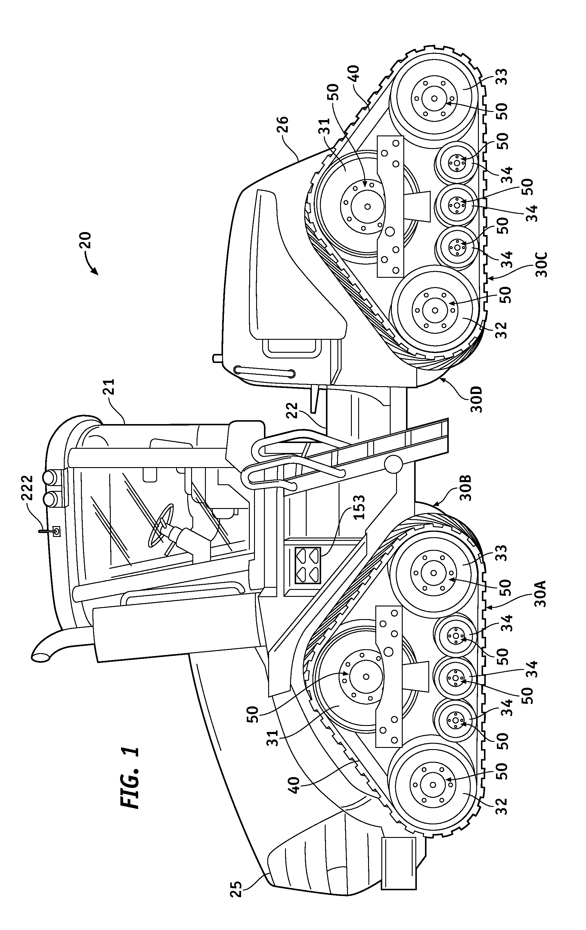
[0022]Turning now to the drawings, in which like reference characters indicate corresponding elements throughout the several views, attention is first directed to FIG. 1 in which there is seen a tracked vehicle 20 that is exemplary of a conventional and well-known articulating tractor including an operator cab 21 supported by a chassis 22 and which is useful for drawing cultivating implements for mechanized cultivating operations as known in the art. Tracked vehicle 20 has a front or leading end denoted generally at 25 and an opposed rear or trailing end denoted generally at 26. Rear end 26 is formed with mechanical and hydraulic couplings (not shown) used to operatively couple selected cultivating implements as is known in the art. Vehicle 20 is formed with track assemblies operable for propelling vehicle 20. In the present embodiment, vehicle 20 is formed with four identical track assemblies including left front track assembly 30A, right front track assembly 30B, left rear track a...


PUM


Abstract

A lubricating oil reservoir has an open end closed by a cap removably coupled to the open end. The cap is formed with a sensor located in the lubricating oil reservoir. The sensor is for sensing the presence of lubricating oil that fills the lubricating oil reservoir to a recommended oil level for providing machine lubrication, and the non-presence of lubricating oil that does not fill the lubricating oil reservoir to the recommended oil level, and a signal apparatus is operatively coupled to the sensor for issuing a first stimulus in response to the sensor sensing the presence of lubricating oil for identifying a normal lubricating oil level condition, and for issuing a second different stimulus in response to the sensor sensing the non-presence of lubricating oil for identifying a low oil level condition.

Description

FIELD OF THE INVENTION[0001]The present invention relates generally to lubricating oil reservoirs for maintaining lubricating oil for providing machine lubrication, to tracked vehicles and also to maintenance caps used to cap lubricating oil reservoirs of rollers of tracked vehicles.BACKGROUND OF THE INVENTION[0002]A crawler-type or tracked vehicle is normally supported and propelled by an undercarriage assembly having an endless track entrained about a drive roller or sprocket, a front idler roller, a rear idler roller, and a series of track rollers. The drive roller or sprocket is driven by an engine of the work vehicle which, in turn, causes the endless track to be advanced around each of the front and rear idler rollers as well as the track rollers to advance the work vehicle.[0003]For an endless track to function properly, it must be properly tensioned around the several rollers, and the several rollers must be properly maintained to ensure they roll with the least amount of fr...

Claims


Application Information

Patent Timeline
IPC IPC(8): F01M11/12
CPCF01M11/12F16N19/003B62D55/092F16N29/00F16N29/02F16N2250/18
Inventor KILE, RONALD J.
Owner KILE RONALD J
Learn More