Exercise Machine Tension System

a technology of tension system and exercise machine, which is applied in the field of exercise machine, can solve the problems of user injury, spring failure of such exercise machine, and user injury

Active Publication Date: 2014-05-01
LAGREE TECH INC
View PDF4 Cites 123 Cited by
  • Summary
  • Abstract
  • Description
  • Claims
  • Application Information

AI Technical Summary

Problems solved by technology

The springs utilized within such exercise machines will eventually fail due to fatigue from the repeated cycles.
Because of the linear nature of these springs and their long length, they will often lose effectiveness fairly quickly through repeated use, particularly when the exercise machine is in a public gym.
When such a spring experiences failure while under tension, the two or more pieces of the fractured spring can behave radically and unpredictably to become projectiles or whips that can cause serious injury to the user.

Method used


Image

  • Exercise Machine Tension System
  • Exercise Machine Tension System
  • Exercise Machine Tension System

Examples


first embodiment

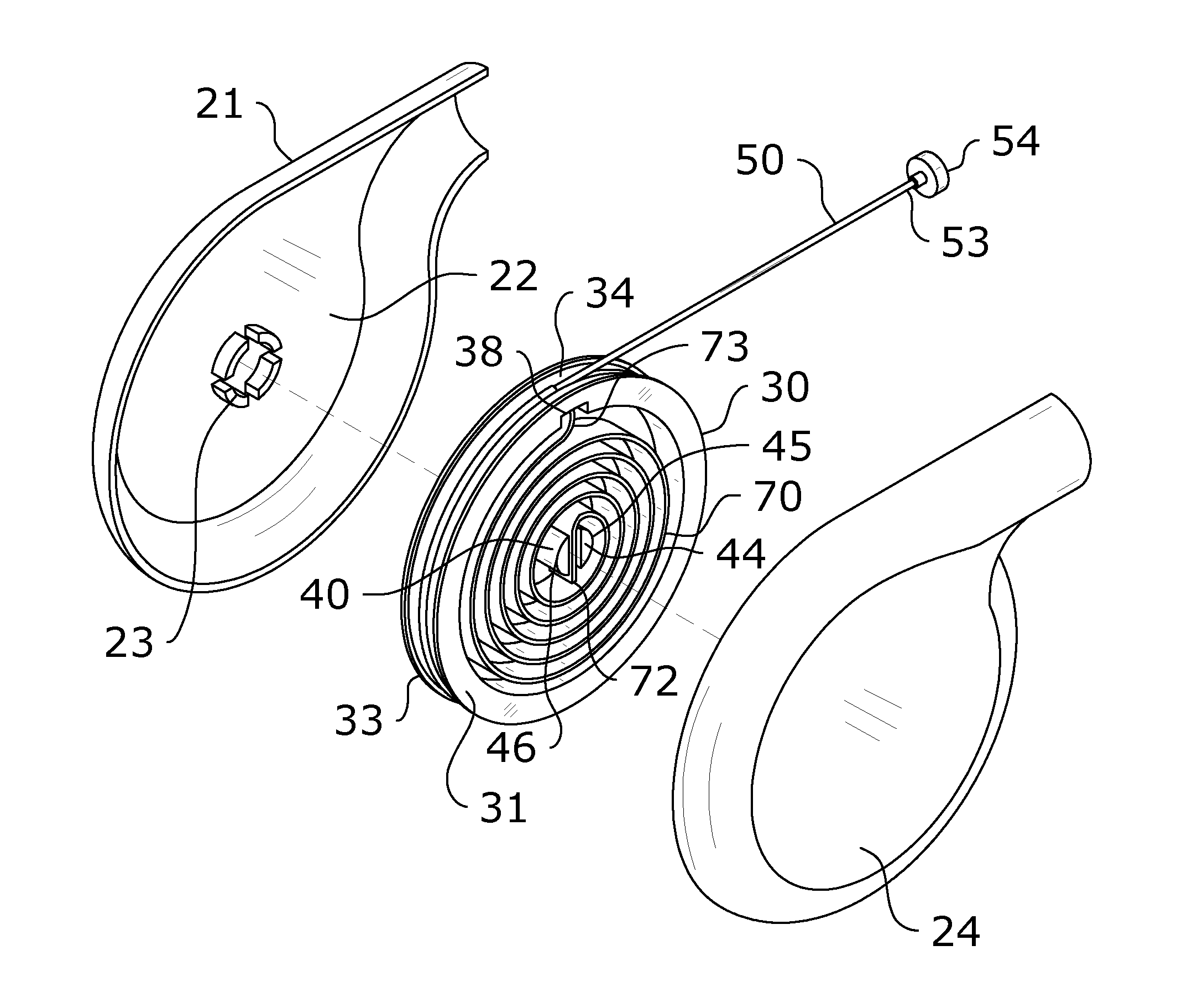
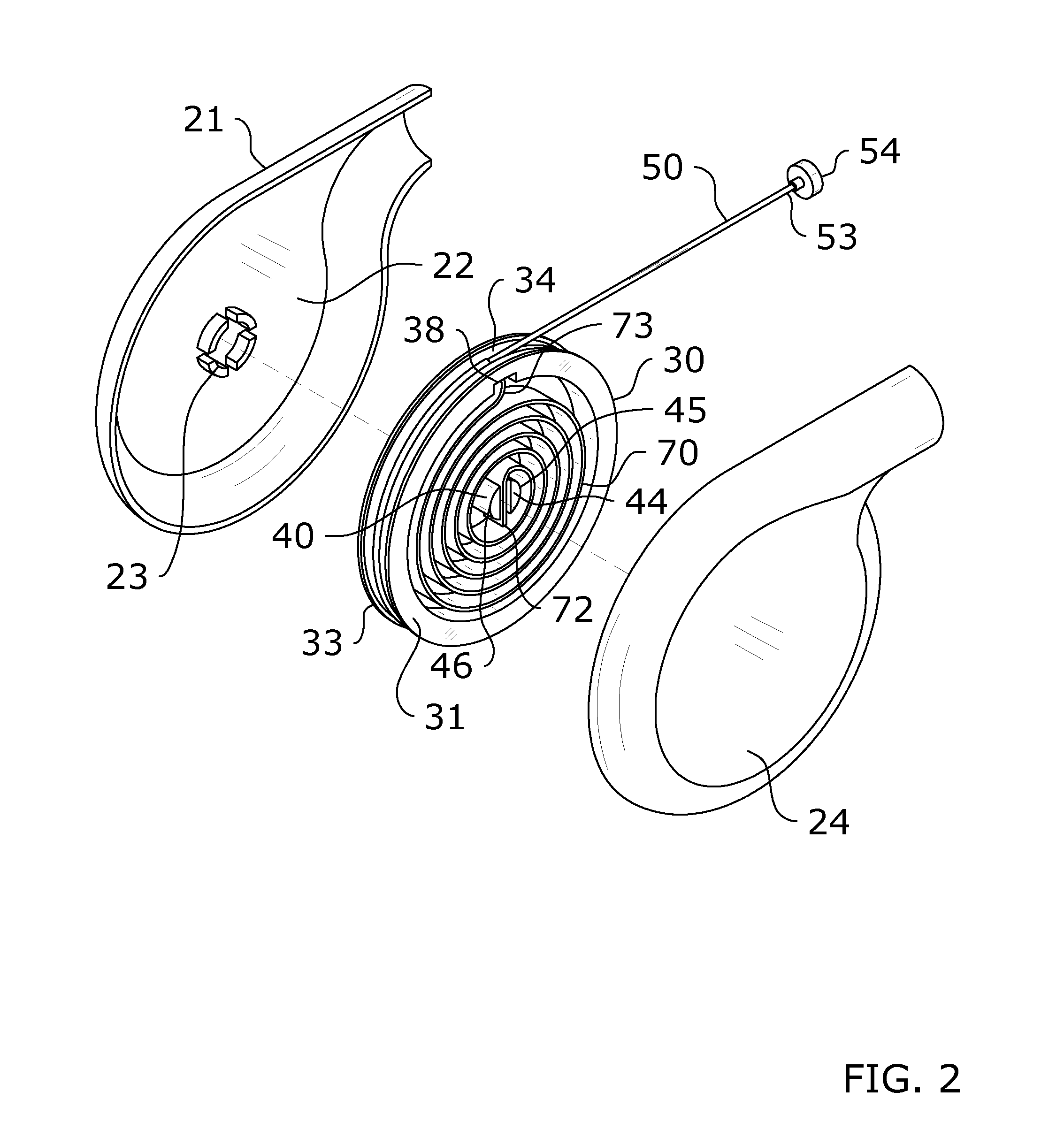
[0049]the reel 30 shown in FIGS. 2-5 includes a groove 34 formed within the outer circumference 33 of the reel 30. The flexible member 50 of the present invention is wound within the groove 34 so as to be unwound therefrom when the reel 30 rotates in a first direction and wound back thereon when the reel 30 rotates in a second direction as shown in FIGS. 2-3.

second embodiment

[0050]the reel 30 shown in FIGS. 8-10 includes a cam 60 positioned on the second side 32 of the reel 30. The cam 60 is generally raised from the second side 32 of the reel 30 and comprised of a substantially triangular configuration with curved corners and bowed outer edges as best shown in FIG. 8. The outer circumference 62 of the cam 60 includes a groove 64. The flexible member 50 of the present invention is wound within the groove 64 so as to be unwound therefrom when the reel 30 rotates in a first direction and wound back thereon when the reel 30 rotates in a second direction.

[0051]The use of a cam 60 reduces the length of the crank arm as measured as the instant radius about the axle, consequently increasing the force required to unwind the flexible member 50 by pulling. By pulling the flexible member 50 from a cam 60 connected to a torsion spring 70, the resistance can be reduced to correspond to the exerciser's relative strength throughout the range of motion. This can substa...


PUM


Abstract

An exercise machine tension system for improving functionality and linear resistance of a Pilates machine. The exercise machine tension system generally includes an exercise machine including a carriage slidably positioned thereon. A plurality of tension units are connected between the exercise machine and the carriage for creating linear resistance as the carriage is drawn in a first direction and reverting the carriage back to its original position absent application of force. Each tension unit includes a housing, a reel rotatably positioned within the housing, a torsion spring secured to the reel, and a flexible member wound around the reel and extending out of the housing. The housing is secured to the exercise machine and the distal end of the flexible member is secured to the carriage.

Description

CROSS REFERENCE TO RELATED APPLICATIONS[0001]I hereby claim benefit under Title 35, United States Code, Section 119(e) of U.S. provisional patent application Ser. No. 61 / 719,763 filed Oct. 29, 2012. The 61 / 719,763 application is currently pending. The 61 / 719,763 application is hereby incorporated by reference into this application.STATEMENT REGARDING FEDERALLY SPONSORED RESEARCH OR DEVELOPMENT[0002]Not applicable to this application.BACKGROUND OF THE INVENTION[0003]1. Field of the Invention[0004]The present invention relates generally to an exercise machine and more specifically it relates to an exercise machine tension system for improving functionality and linear resistance of a Pilates machine.[0005]2. Description of the Related Art[0006]Any discussion of the related art throughout the specification should in no way be considered as an admission that such related art is widely known or forms part of common general knowledge in the field.[0007]Exercise machines are becoming increa...

Claims


Application Information

Patent Timeline
Patent Type & Authority Applications(United States)
IPC IPC(8): A63B21/02
CPCA63B21/025A63B21/00065A63B21/153A63B22/0089
Inventor LAGREE, SEBASTIEN ANTHONY LOUISHAMILTON, JOHN C.GIBBS, ANDY H.
Owner LAGREE TECH INC
Why Eureka
Try Eureka