Inflatable prostheses and methods of making same

a prosthesis and inflatable technology, applied in the field of medical implants, can solve the problems of difficult to develop a flexible protective material, difficulty in developing and touch-invasion of valves or filling ports

Inactive Publication Date: 2014-05-01
ALLERGAN INC
View PDF17 Cites 10 Cited by
  • Summary
  • Abstract
  • Description
  • Claims
  • Application Information

AI Technical Summary

Benefits of technology

[0042]Advantageously, the misaligned or overlapping members of the adjacent composite guards provide a puncture resistant, or puncture proof, area while not significantly sacrificing flexibility of the assembly as a whole. That is, the composite guards may be arranged such that there are no significant gaps between individual puncture resistant members. It can be appreciated that depending upon the use of the final assembly, there may be some gaps between members so long as the gaps are sufficiently narrow to resist or prevent penetration by the type of instrument that the assembly is intended to be protected against puncture from.
[0043]In any event, in some embodiments of the invention, the puncture resistant members of the composite guards may provide an area of protection that substantially entirely covers a first side of the needle guard assembly.
[0044]The assembly may further comprise a intermediate layer, for example, an elastomer, securing together the first and second composite guards such that the members maintain their offset relationship. The intermediate layer may be located between adjacent composite guards and may be bonded thereto. In one embodiment, the intermediate layer seals the flexible composite members together and encapsulates the composite guards. For example, the intermediate layer may be an fluid tight barrier containing the two or more layered composite guards. In some embodiments, the intermediate layer exhibits a springiness and resiliency or provides a shape memory characteristic to the assembly.

Problems solved by technology

Unfortunately, the valve or fill port is sometimes noticeable to the touch.
One problem with many conventional adjustable implants is that they require a valve to be part of the implant.
It has also proven difficult to develop a flexible protective material that is effective as a puncture resistant material while also being safe for implantation in the body.

Method used


Image

  • Inflatable prostheses and methods of making same
  • Inflatable prostheses and methods of making same
  • Inflatable prostheses and methods of making same

Examples


Embodiment Construction

[0074]The present invention generally pertains to implantable inflatable devices and methods for making same, for example, devices such as soft fluid-filled implants, for example, but not limited to, permanent or temporary implants useful in breast reconstruction or breast augmentation procedures.

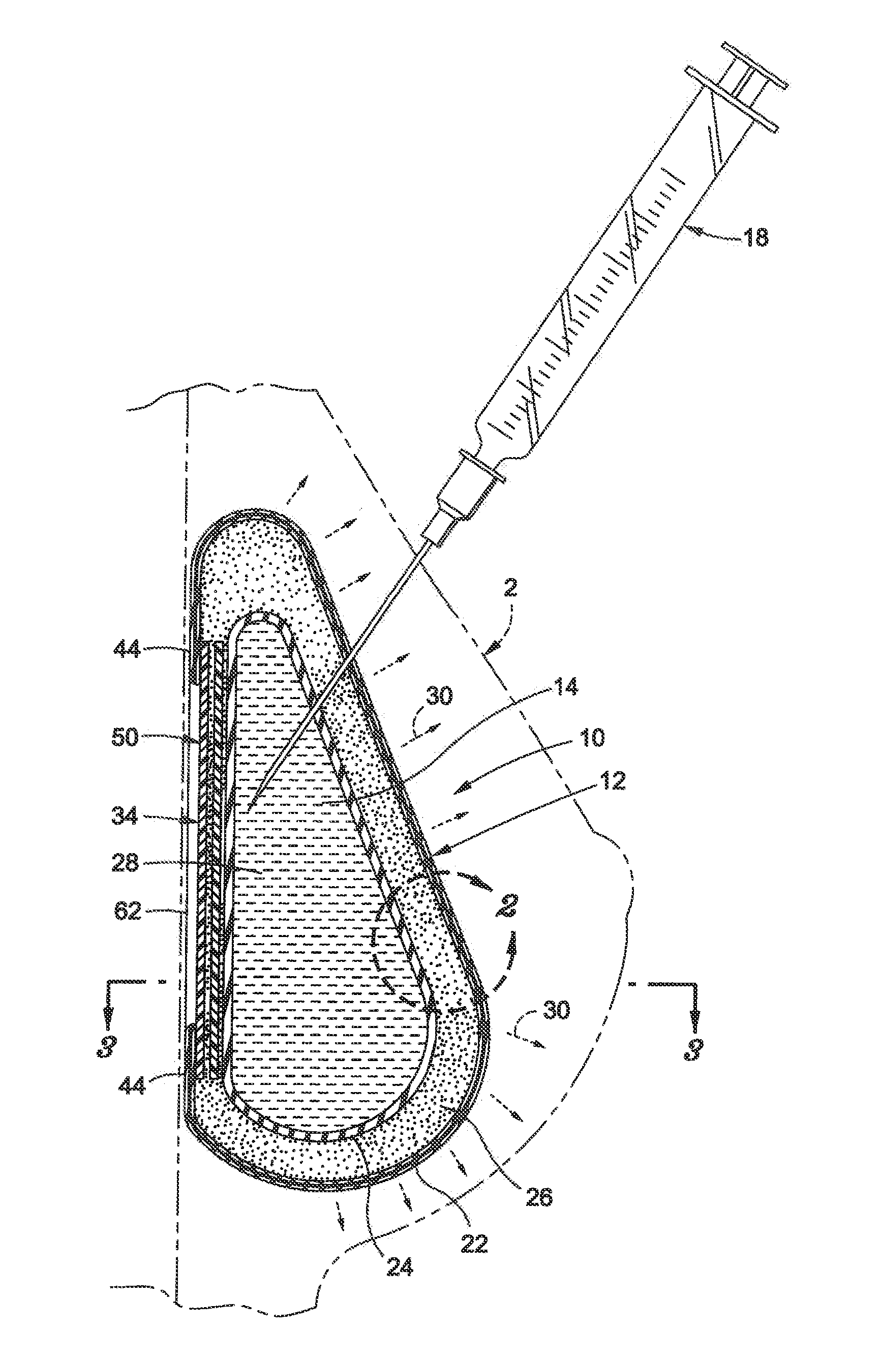
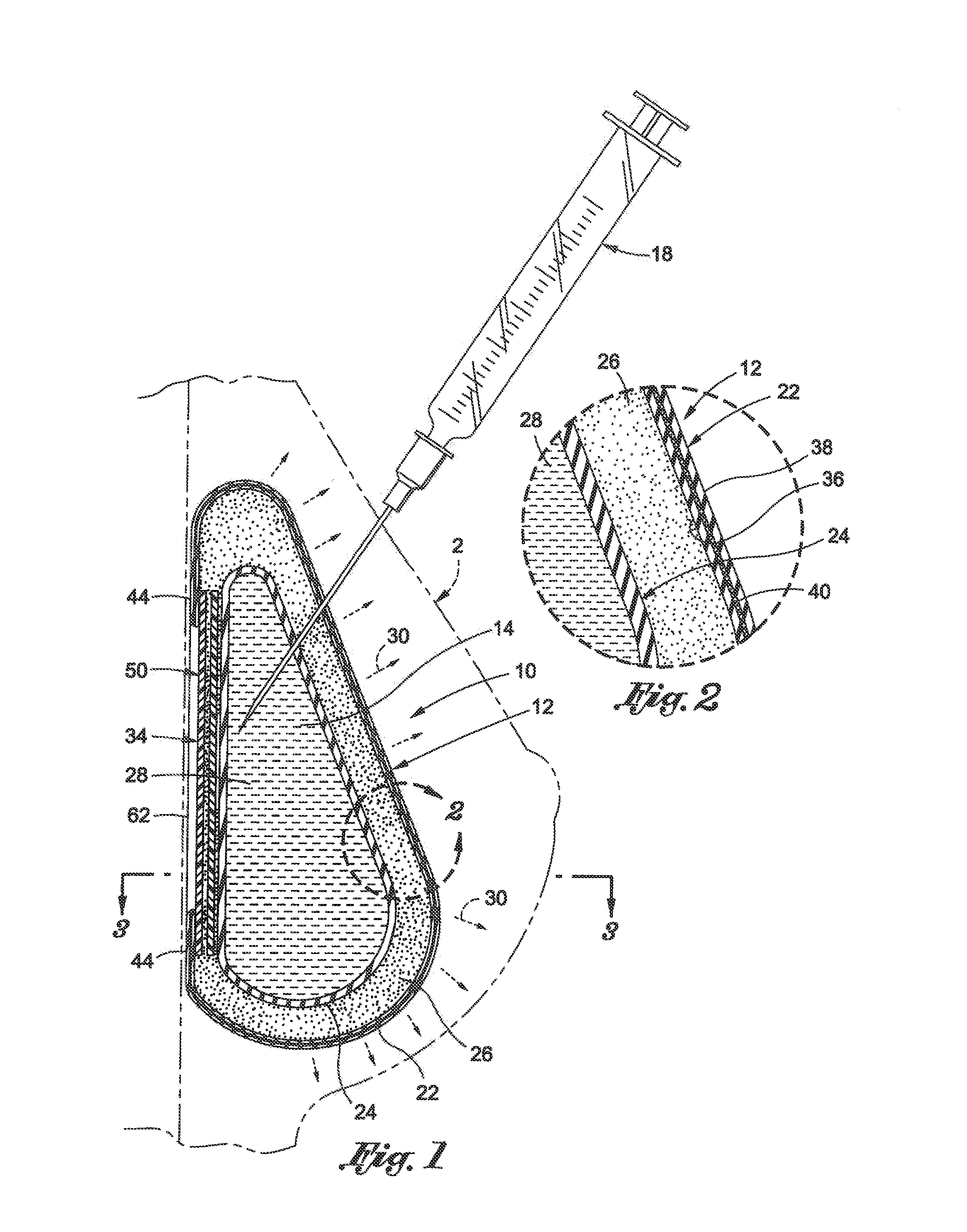
[0075]Turning now to FIG. 1, an inflatable device, in accordance with one embodiment of the invention, is shown generally at 10, as implanted in a human breast 2. The device 10 is being inflated with a suitable fluid, such as a saline solution 14, by means of a typical syringe 18.

[0076]The device 10 generally comprises an inflatable portion 12 comprising outer shell 22, an inner shell 24 and a intermediate layer 26 therebetween. The inner shell 24 defines an inflatable cavity 28 (shown here as being filled with saline solution 14).

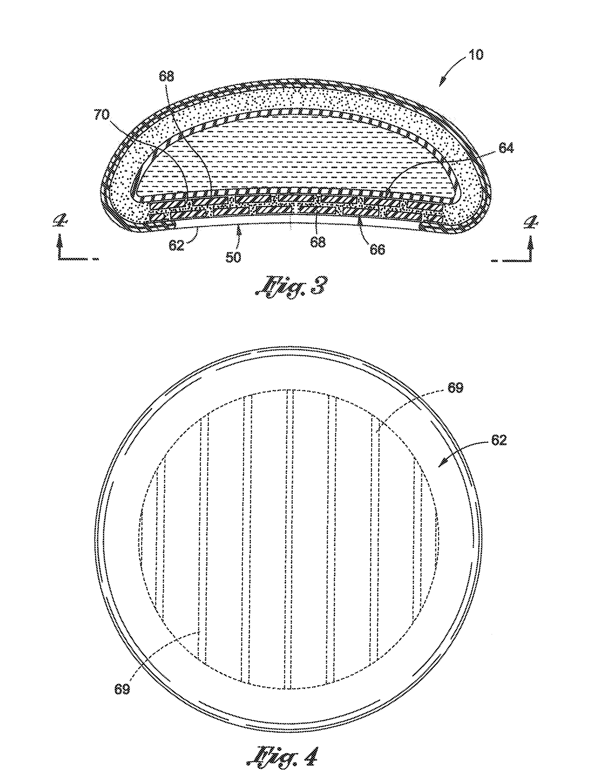
[0077]Inflation of the cavity 28 causes expansion of the device as shown by arrows 30. The device 10 further includes a posterior portion 34 that is generally res...


PUM


Abstract

An inflatable tissue expander or more permanent prosthesis, suitable for implantation in a breast, is provided. The tissue expander includes a puncturable, self-sealing anterior portion forming a fillable cavity, and posterior portion that is puncture resistant. The anterior portion includes a silicone-based elastomer material having a mesh embedded therein. The posterior portion includes a first composite guard and a second composite guard, each composite guard including an arrangement of puncture resistant members and a flexible substrate having a first side on which the puncture resistant members are disposed in a spaced apart fashion.

Description

RELATED APPLICATIONS[0001]This application is a continuation of U.S. patent application Ser. No. 13 / 105,715, filed May 11, 2011, which is a continuation-in-part of U.S. patent application Ser. No. 13 / 021,523, filed on Feb. 4, 2011, which claims the benefit of U.S. Provisional Patent Application No. 61 / 301,910, filed on Feb. 5, 2010, and the benefit of U.S. Provisional Patent Application No. 61 / 409,440, filed on Nov. 2, 2010, the entire disclosure of each of these applications being incorporated herein in its entirely by this reference.BACKGROUND INFORMATION[0002]The present invention generally relates to medical implants and more specifically relates to inflatable prostheses, such as tissue expanders, suitable for implantation in a mammal.[0003]Prostheses or implants for reconstruction and / or augmentation of the human body are well known.[0004]Fluid filled prostheses, for example, mammary prostheses or breast implants, are widely used to replace excised tissue, for example after a r...

Claims


Application Information

Patent Timeline
Patent Type & Authority Applications(United States)
IPC IPC(8): A61F2/12
CPCA61F2/12A61F2250/0003A61F2250/0004A61B90/02A61F2210/0076A61F2/76
Inventor CHITRE, KAUSTUBH S.MANESIS, NICHOLAS J.TRILOKEKAR, NIKHILLESLIE, DUSTINSCHUESSLER, DAVID
Owner ALLERGAN INC
Why Eureka
Try Eureka