
Track suspension

a suspension and track technology, applied in the direction of belts/chains/gearrings, mechanical devices, belts/chains/gearrings, etc., can solve the problems of excessive vehicle parts wear, less comfort, force to be transmitted to the vehicle by idlers and roller wheels

Active Publication Date: 2014-05-08
LOC PERFORMANCE PROD LLC
View PDF10 Cites 31 Cited by
  • Summary
  • Abstract
  • Description
  • Claims
  • Application Information

AI Technical Summary

Benefits of technology

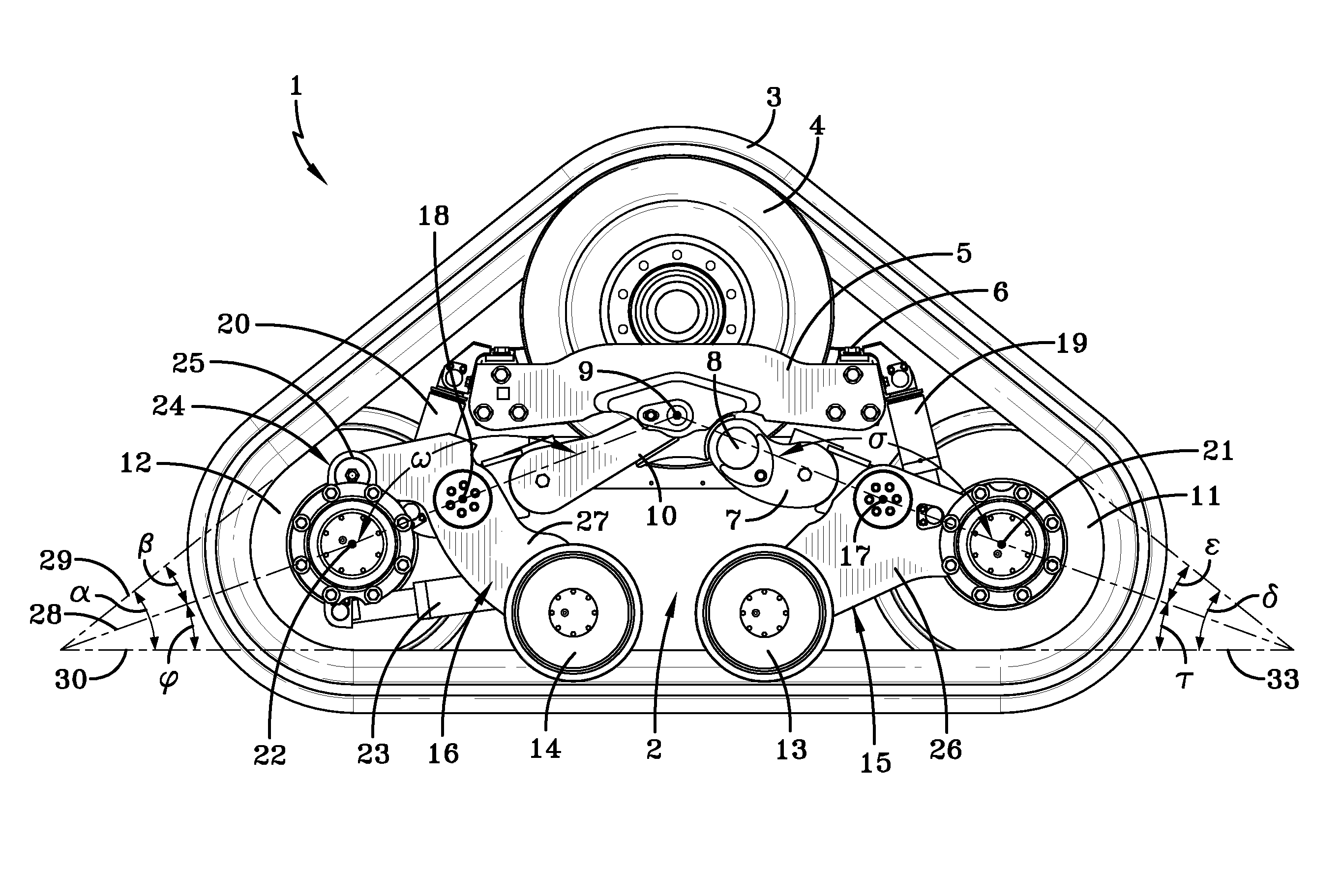
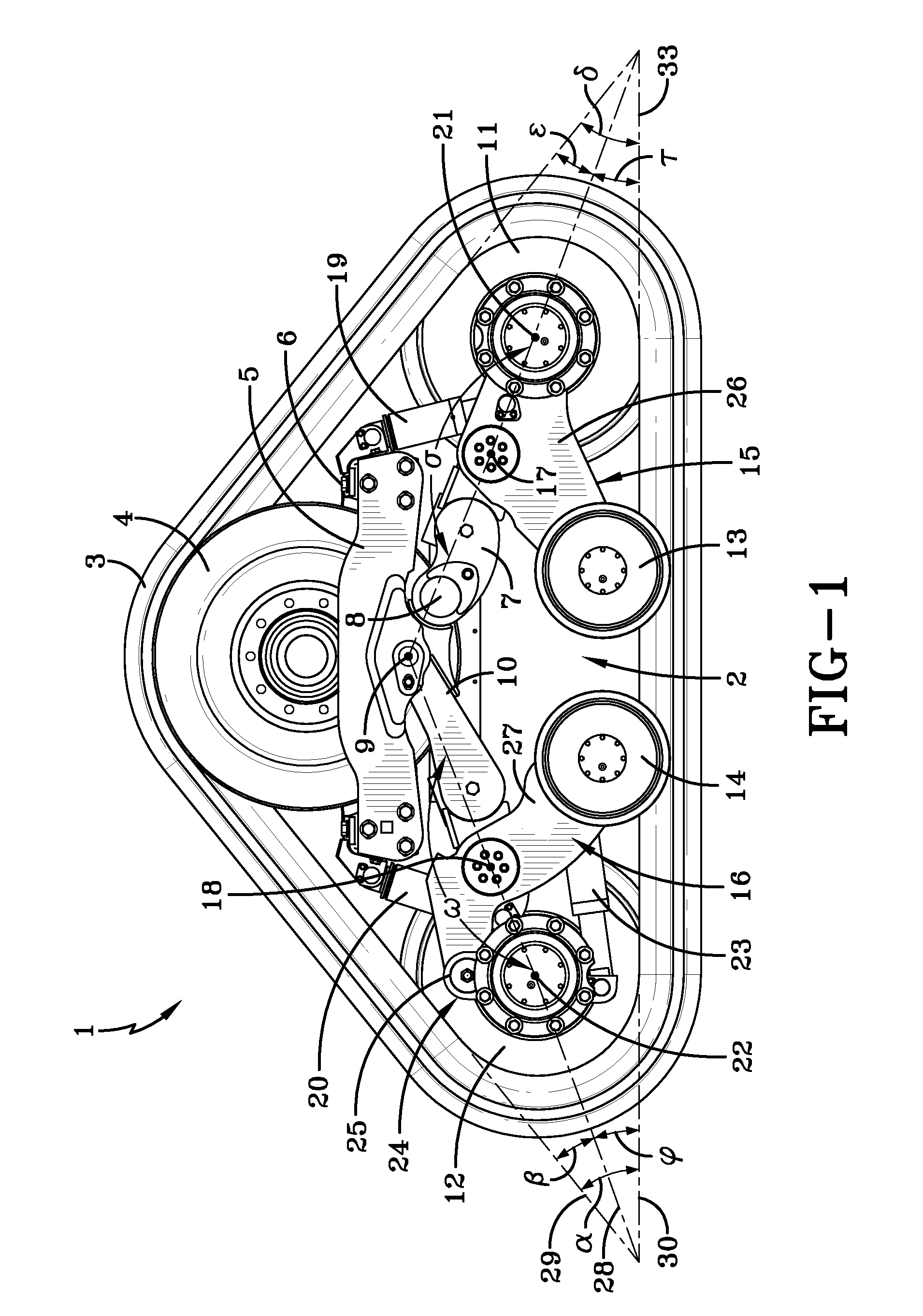
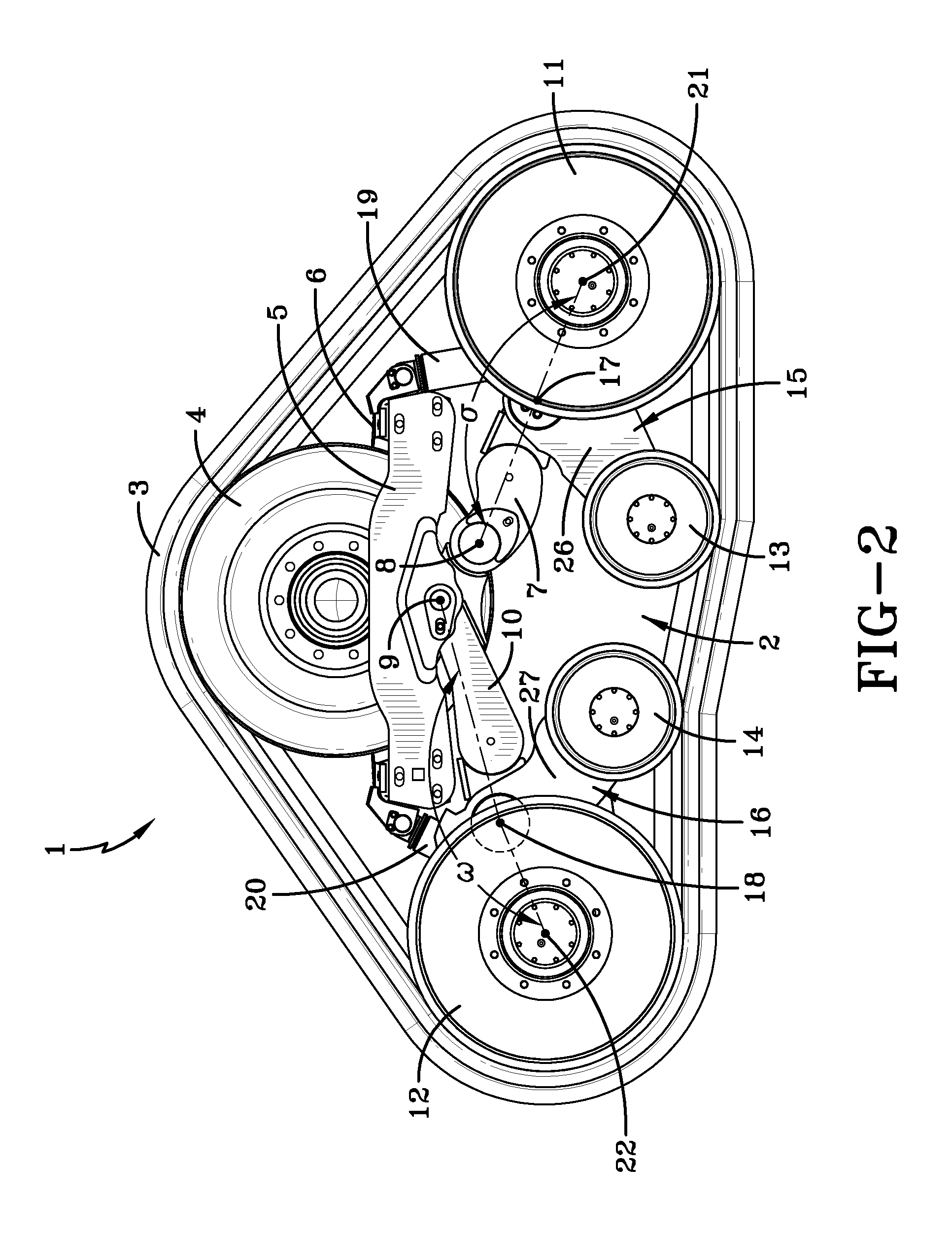
The present invention is a track suspension system for a vehicle that includes a drive wheel, yoke plate carrier, front and rear wishbone members, front and rear rocker assemblies, front and rear suspension spring assemblies, and track tensioning rocker and cylinder. The system allows for improved vehicle performance and stability while driving on different terrains. The front and rear rocker assemblies are connected to the yoke assembly through a front and rear wishbone joint, which allows for better alignment and reduced friction. The front and rear suspension spring assemblies are also connected to the yoke assembly, providing better load distribution and reduced stress. The track tensioning rocker and cylinder ensure proper track tensioning for optimal performance. Overall, the track suspension system provides improved vehicle performance and stability while driving on different terrains.

Problems solved by technology

Track driven vehicles are commonly very heavy vehicles that require a substantial load to be carried by each track and track suspension on the vehicle.
The lack of articulation of the idler and roller wheels limits the tractive force of the track and also causes forces to be transmitted to the vehicle from the idler and roller wheels.
This lack of articulation can make the ride less comfortable for the driver of the track driven vehicle and in some cases can lead to excessive vehicle part wear.

Method used


Image

  • Track suspension
  • Track suspension
  • Track suspension

Examples


example 1

[0065]A track suspension system comprising a rubber track which is adapted to be ground contacting will be attached to an agricultural vehicle. A drive wheel will be rotatably affixed to and driven by a vehicle final drive axle assembly. The drive wheel will be adapted for engaging and driving the rubber track. A yoke plate carrier will be affixed to a yoke assembly.

[0066]A rear wishbone member will be rotatably affixed to the yoke assembly and the yoke plate carrier through a rear wishbone joint. A front wishbone member will be rotatably affixed to the rear wishbone member through a front wishbone joint. A front rocker assembly, which is comprised of a front rocker beam, a front idler wheel and a front roller wheel will be rotatably affixed to the front wishbone through a front rocker joint. A rear rocker assembly which is comprised of a rear rocker beam, a rear roller wheel and a rear idler wheel will be rotatably affixed to the rear wishbone member through a rear rocker joint.

[00...


PUM


Abstract

This invention discloses a track suspension wherein a rear wishbone member is rotatably affixed to a yoke assembly and a yoke plate carrier through a rear wishbone joint, wherein a front wishbone member is rotatably affixed to the rear wishbone member through a front wishbone joint, wherein a rear rocker assembly is comprised of a rear rocker beam, a rear roller wheel and a rear idler wheel, wherein a front rocker beam is rotatably affixed to the front wishbone through a front rocker joint, wherein the rear rocker beam is rotatably affixed to the rear wishbone member through a rear rocker joint, wherein a front suspension spring assembly is affixed between a yoke assembly and a front wishbone member, and wherein a rear suspension spring assembly is affixed between the yoke assembly and the rear wishbone member.

Description

[0001]This application claims benefit of U.S. Provisional Patent Application Ser. No. 61 / 721,602, filed on Nov. 2, 2012. The teachings of U.S. Provisional Patent Application Ser. No. 61 / 721,602 are incorporated herein by reference in their entirety.FIELD OF THE INVENTION[0002]The present invention is in the field of suspensions for vehicles. More specifically this invention relates to suspensions for vehicles utilizing a track drive system.BACKGROUND OF THE INVENTION[0003]Track driven vehicles are commonly used in the agricultural and construction industries. Track driven vehicles are commonly very heavy vehicles that require a substantial load to be carried by each track and track suspension on the vehicle. For this reason, prior art suspensions have minimal travel and articulation to idler and roller wheels in contact with the track. The lack of articulation of the idler and roller wheels limits the tractive force of the track and also causes forces to be transmitted to the vehicl...

Claims


Application Information

Patent Timeline
Patent Type & Authority Applications(United States)
IPC IPC(8): B62D55/14B62D55/30
CPCB62D55/305B62D55/14B62D55/104B62D55/112
Inventor NAGORCKA, JAMES A.ALLEN, LYAL D.
Owner LOC PERFORMANCE PROD LLC
Learn More