Image processing device and image processing method

a technology of image processing and image processing, applied in the direction of signal generator with optical-mechanical scanning, color television with bandwidth reduction, etc., can solve the problem of not optimal setting the size of a macroblock to 1616 pixels, and achieve the effect of suppressing the decrease in encoding efficiency

Active Publication Date: 2014-05-08
SONY CORP
View PDF9 Cites 27 Cited by
  • Summary
  • Abstract
  • Description
  • Claims
  • Application Information

AI Technical Summary

Benefits of technology

[0047]According to the present disclosure, it is possible to process images. In particular, it is possible to suppress a decrease in encoding efficiency.

Problems solved by technology

However, setting the size of a macroblock to 16×16 pixels is not optimal for a large image frame named UHD (Ultra High Definition; 4000×2000 pixels) that will become an object of the next generation encoding scheme.

Method used


Image

  • Image processing device and image processing method
  • Image processing device and image processing method
  • Image processing device and image processing method

Examples


first embodiment

1. First Embodiment

Motion Prediction

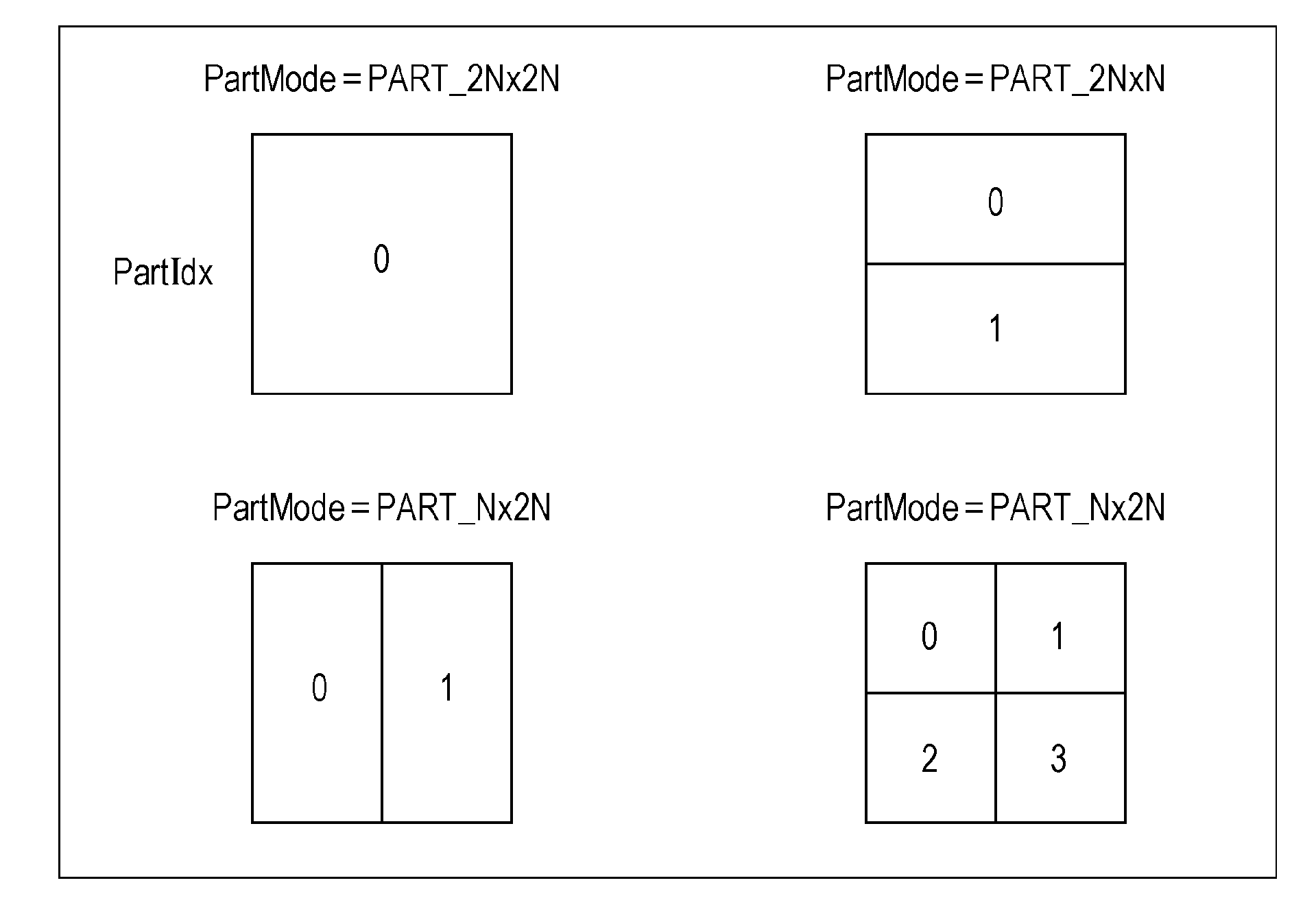
[0156]In image encoding such as AVC (Advanced Video Coding) or HEVC (High Efficiency Video Coding), motion prediction using correlation in the temporal direction (between frames) is performed.

[0157]The AVC defines layered blocks such as macroblocks or sub-macroblocks as processing units of such a prediction process, and the HEVC defines coding units (CUs).

[0158]The CU which is also called a coding tree block (CTB) is a partial region of a picture-base image, which plays the same role as the macroblock in the AVC. The size of the macroblock is fixed to 16×16 pixels whereas the size of the CU is not fixed but is designated in image compression information in respective sequences.

[0159]For example, the largest size (LCU: Largest Coding Unit) and the smallest size (SCU: Smallest Coding Unit) of the CU are defined in a sequence parameter set (SPS) included in output encoded data.

[0160]Each LCU can be split into CUs of the smaller size that is not small...

second embodiment

2. Second Embodiment

Image Decoding Device

[0365]FIG. 31 is a block diagram illustrating a main configuration example of an image decoding device which is an image processing device. An image decoding device 300 illustrated in FIG. 31 is a device that corresponds to the image encoding device 100 of FIG. 11. That is, the image decoding device 300 decodes the encoded data (bit stream), which is generated through encoding a multi-view image by the image encoding device 100, according to a decoding method corresponding to the encoding method of the image encoding device 100 to obtain a decoded multi-view image.

[0366]As illustrated in FIG. 31, the image decoding device 300 includes an accumulation buffer 301, a lossless decoding unit 302, an inverse quantization unit 303, an inverse orthogonal transform unit 304, an arithmetic unit 305, a loop filter 306, a screen rearrangement buffer 307, and a D / A converter 308. Moreover, the image decoding device 300 includes a decoded picture buffer 30...

third embodiment

3. Third Embodiment

Point

[0422]In the case of multi-view images, the positions of images are offset between views so that a parallax occurs. Thus, when a block in the view direction is selected, even if a block at the same position is selected (referred to), the prediction accuracy of the predicted image may decrease and there is a possibility that it is not possible to create an appropriate predictive vector.

[0423]Thus, when a block in the view direction is selected in order to generate a predictive vector, a block at a shifted position is selected. That is, the predictive vector is generated using a vector of such a region that is located at the same position as the current region in a state where the position of an image of the same time as the current region is shifted.

[0424]The shift amount is calculated in a predetermined order from the parallax vector of the neighboring block. By using the same order in both an encoding-side device and a decoding-side device, the same predicti...


PUM


Abstract

The present technique relates to an image processing device and method capable of suppressing a decrease in encoding efficiency. The image processing device includes: a predictive vector generating unit that generates a predictive vector of a current parallax vector of a current block used in prediction using correlation in a parallax direction using a reference parallax vector referred when generating a predictive motion vector, when encoding the current parallax vector; and a difference vector generating unit that generates a difference vector between the current parallax vector and the predictive vector generated by the predictive vector generating unit. The present disclosure can be applied to an image processing device.

Description

TECHNICAL FIELD[0001]The present disclosure relates to an image processing device and an image processing method. Specifically, the present disclosure relates to an image processing device and an image processing method capable of improving encoding efficiency.BACKGROUND ART[0002]In recent years, devices, which handle image information as digital data, which, in such a case, aim to transmit and store information with a high efficiency, and which conform to a scheme such as MPEG (Moving Picture Experts Group), for compressing image information using orthogonal transformation, such as discrete cosine transformation, and using motion compensation by utilizing redundancy that is unique to the image information have become widespread in both information distribution in broadcasting stations and information reception in ordinary homes.[0003]In particular, MPEG2 (International Organization for Standardization and International Electrotechnical Commission (ISO / IEC) 13818-2) is defined as a ...

Claims


Application Information

Patent Timeline
Patent Type & Authority Applications(United States)
IPC IPC(8): H04N19/597H04N19/593H04N19/51
CPCH04N19/00769H04N19/00763H04N19/00684H04N19/503H04N19/513H04N19/52H04N19/593H04N19/597H04N19/172H04N19/176H04N19/105H04N19/119H04N19/184H04N13/00H04N19/117H04N19/124H04N19/15H04N19/159H04N19/30H04N19/61
Inventor TAKAHASHI, YOSHITOMOHATTORI, SHINOBU
Owner SONY CORP
Why Eureka
Try Eureka