
Technical field of method of controlling electric vehicle and drive system of electric vehicle

Pending Publication Date: 2022-04-21
NISSAN MOTOR CO LTD
View PDF0 Cites 3 Cited by
  • Summary
  • Abstract
  • Description
  • Claims
  • Application Information

AI Technical Summary

Benefits of technology

The patent text describes a configuration where a second clutch is added between the travel motor and the drive wheel to improve efficiency. This second clutch, sometimes referred to as a detent, is engaged when the vehicle is in direct connected mode with the engine disengaged, to prevent rotation of the travel motor and improve overall efficiency.

Problems solved by technology

With such a configuration, the friction caused by the travel motor becomes a load for propelling the vehicle, and thus, there is a risk in that an overall system efficiency is deteriorated and an electric mileage, which is a distance that the vehicle can travel par a unit electric power, is lowered.
That is, when the engine direct connected mode is switched to a series hybrid mode in which the travel motor is used as the drive power source, there is a risk in that, depending on a travelling state during the switching, crossover between the engagement-side clutch and the disengagement-side clutch may not be achieved smoothly and a drivability may be deteriorated.

Method used


Image

  • Technical field of method of controlling electric vehicle and drive system of electric vehicle
  • Technical field of method of controlling electric vehicle and drive system of electric vehicle
  • Technical field of method of controlling electric vehicle and drive system of electric vehicle

Examples


Embodiment Construction

[0022]Embodiments of the present invention will be described below with reference to the drawings.

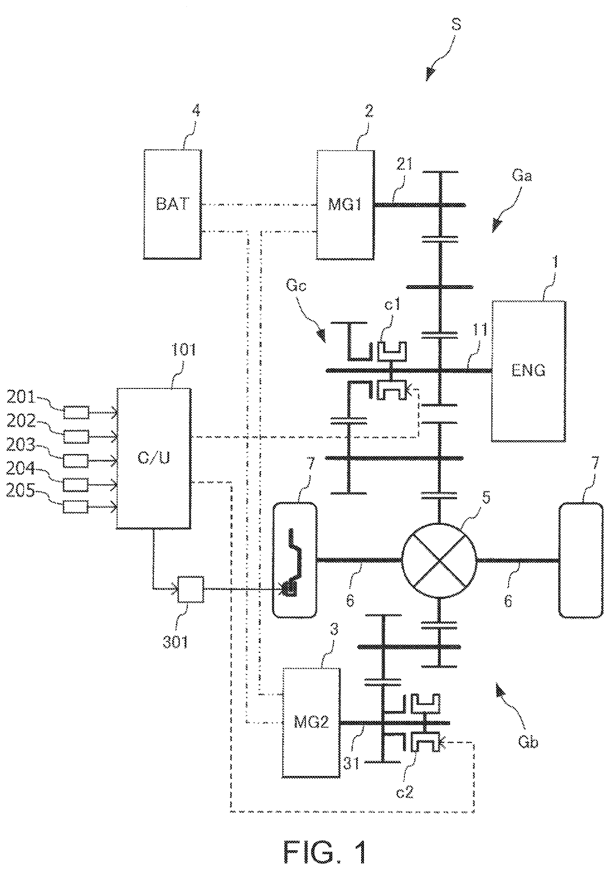
[0023]FIG. 1 shows an overall configuration of a drive system S of an electric vehicle according to an embodiment of the present invention.

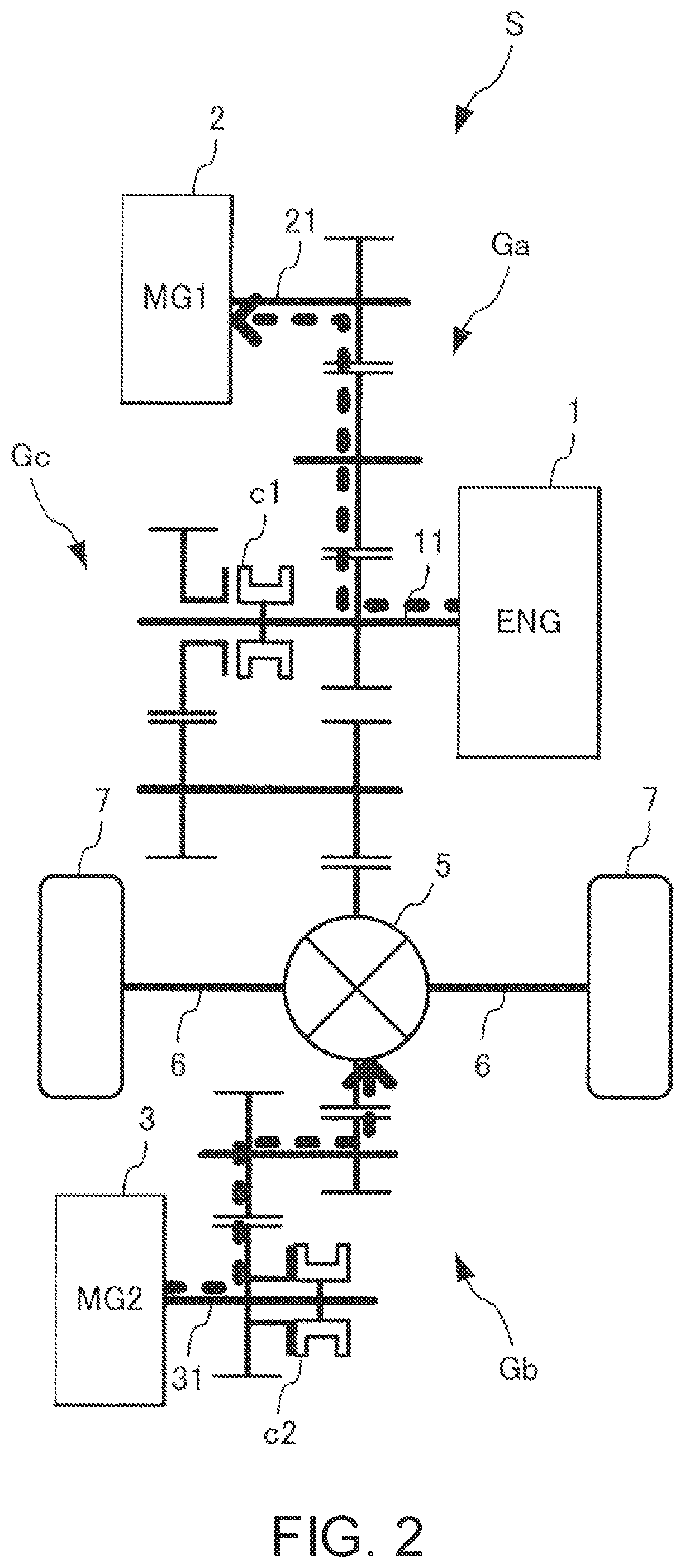
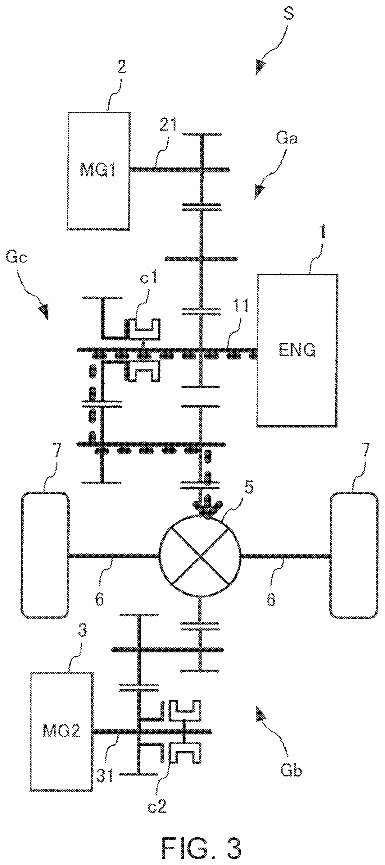
[0024]The drive system according to this embodiment (hereinafter, simply referred to as “a drive system”) S is mounted on the electric vehicle and forms a propulsion apparatus of the vehicle. The drive system S includes an internal combustion engine 1, an electric motor for generating electricity (hereinafter, referred to as “a generating motor”) 2, and an electric motor for travelling (hereinafter, referred to as “a travel motor”) 3.

[0025]An output shaft or a crankshaft 11 of the internal combustion engine (hereinafter, simply referred to as “an engine”) 1 is connected to a rotation shaft 21 of the generating motor 2 via a gear train Ga formed of a plurality of gears. The torque from the engine 1 is transmitted to the generating motor 2 via the gear...


PUM


Abstract

A drive system of an electric vehicle includes: an internal combustion engine; a generating motor provided so as to be able to generate electricity by receiving motive force from the internal combustion engine; and a travel motor provided so as to be able to be driven by electric power generated by the generating motor, and the drive system is configured so as to be able to switch a series hybrid mode and an engine direct connected mode, the series hybrid mode being a mode in which, while the internal combustion engine and the drive wheel are linked via a first clutch so as to be unlinkable / linkable, the travel motor and the drive wheel are linked via a second clutch different from the first clutch so as to be unlinkable / linkable, and the travel motor is used as a drive power source such that the electric vehicle travels by transmitting motive force from the travel motor to the drive wheel, the engine direct connected mode being a mode in which at least one of the internal combustion engine and the generator is used as a drive power source such that the electric vehicle travels by transmitting motive force from the drive power source to the drive wheel. At a mode switching time from the engine direct connected mode to the series hybrid mode involving deceleration, when the rotation synchronization or the engagement of the second clutch on an engagement side is not completed before the vehicle speed is decelerated to a predetermined vehicle speed, the first clutch on a disengagement side is disengaged before the engagement of the second clutch is completed.

Description

TECHNICAL FIELD[0001]The present invention relates to a control method and a drive system of an electric vehicle that is configured so as to be capable of traveling by switching a series hybrid mode and an engine direct connected mode.BACKGROUND ART[0002]A series hybrid type drive system that is configured so as to drive a generator by a motive force from an internal combustion engine and to use electric power generated by this generator to operate an electric motor for travelling (hereinafter, referred to as “a travel motor”) is known. As such a drive system, JP2004-123060A discloses one having a configuration in which the internal combustion engine and a drive wheel are linked via a clutch and the motive force from the internal combustion engine can be transmitted to the drive wheel by bypassing the travel motor (see FIG. 7).SUMMARY OF INVENTION[0003]With the technique disclosed by JP2004-123060A, in a case in which a vehicle is traveled in an engine direct connected mode in which...

Claims


Application Information

Patent Timeline
IPC IPC(8): B60W20/20B60W20/40B60K6/442
CPCB60W20/20B60W20/40B60K6/442B60Y2200/92B60W2540/12B60W2520/12B60W2510/0208B60W2520/105B60W2520/125B60W2520/10B60K6/387B60W10/02B60W10/08Y02T10/62B60W10/06B60W10/184B60W30/18109
Inventor KAGAYA, TAKAYUKIKOGA, MASATONAKAJIMA, YUUKITANAKA, KATSUNORIIWASAKI, TETSUYA
Owner NISSAN MOTOR CO LTD
Learn More