
Fashion Accessory Internal Door Storage Cavity

Inactive Publication Date: 2014-05-15
THOMAS VICKY RENEE
View PDF13 Cites 23 Cited by
  • Summary
  • Abstract
  • Description
  • Claims
  • Application Information

AI Technical Summary

Benefits of technology

The present invention is a storage compartment that can be added to an existing door, allowing for easy storage of articles in a compact way. The system also includes a hollow space within the door that allows for additional storage, as well as an interior panel that can be locked to control access to certain items. Overall, the invention improves storage space in a home while also providing a more usable surface area for organization.

Problems solved by technology

These devices, however, are not optimally structured to maximize the amount of storage for the space provided, nor do they provide an improved means of organizing fashion accessories or similar articles.
The Matselboba device does not extend rearwardly from the closet door, which significantly limits the available storage space, while its door entry is a door gate that opens using two doors that spread apart to gain access to the hollow interior.
The door closet and closet box both have handles that are similar to that provided in the Matselboba device, which are less than ideal given the additional space that the handles take up within the room.
The Zagata devices also fails to provide efficient storage of accessories and hands-free viewing thereof and fails to anticipate an interior panel with a discreet locking means.
The storage space is located only against the back wall of the storage container, which does not maximize the space within the storage container.
The devices disclosed in the prior art do not address the need for maximizing the storage space that is available through a storage space within the hollow of a door, and furthermore do not provide a means of concealing access to the interior compartment using a discreet locking means therealong.

Method used


Image

  • Fashion Accessory Internal Door Storage Cavity
  • Fashion Accessory Internal Door Storage Cavity
  • Fashion Accessory Internal Door Storage Cavity

Examples


Embodiment Construction

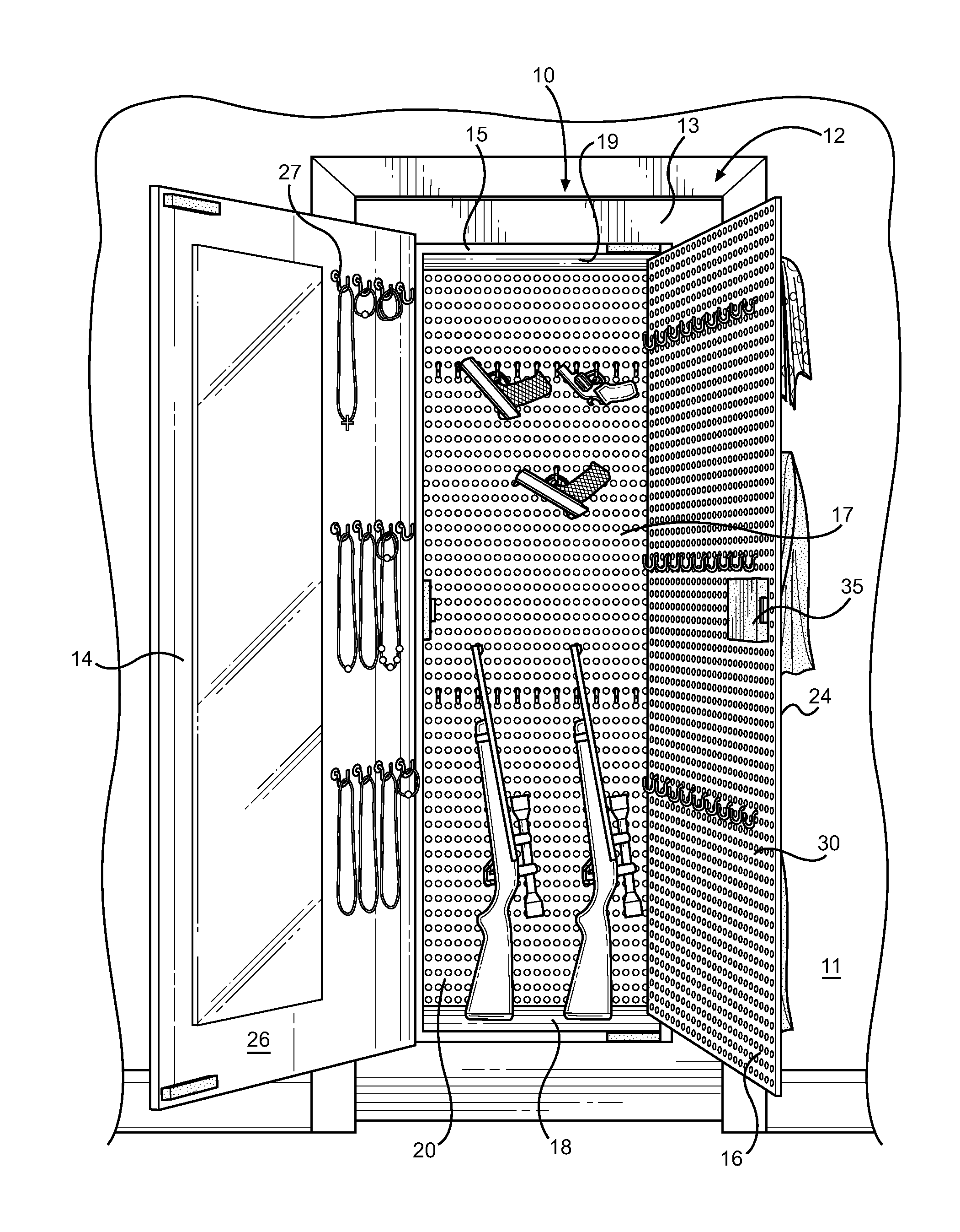
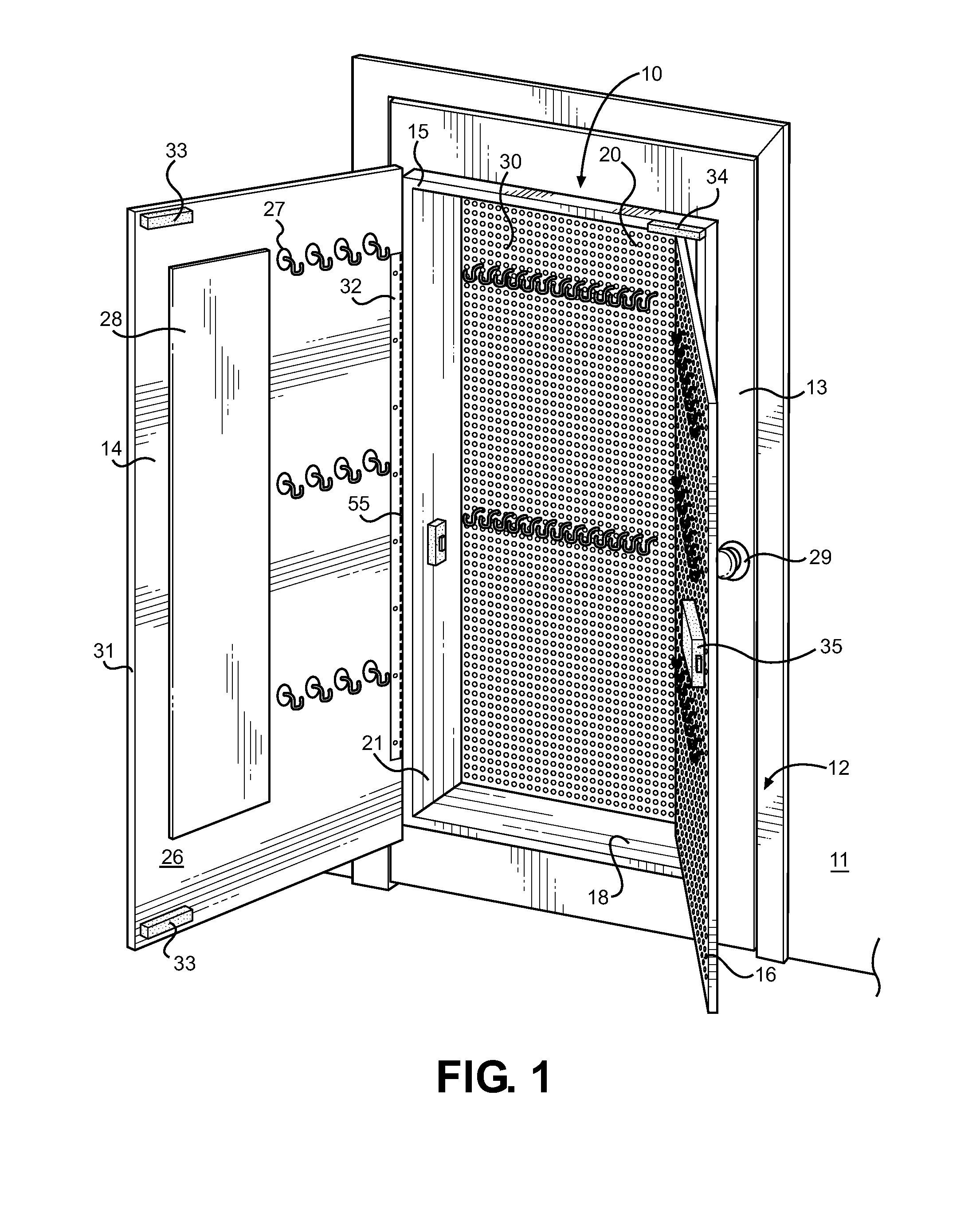
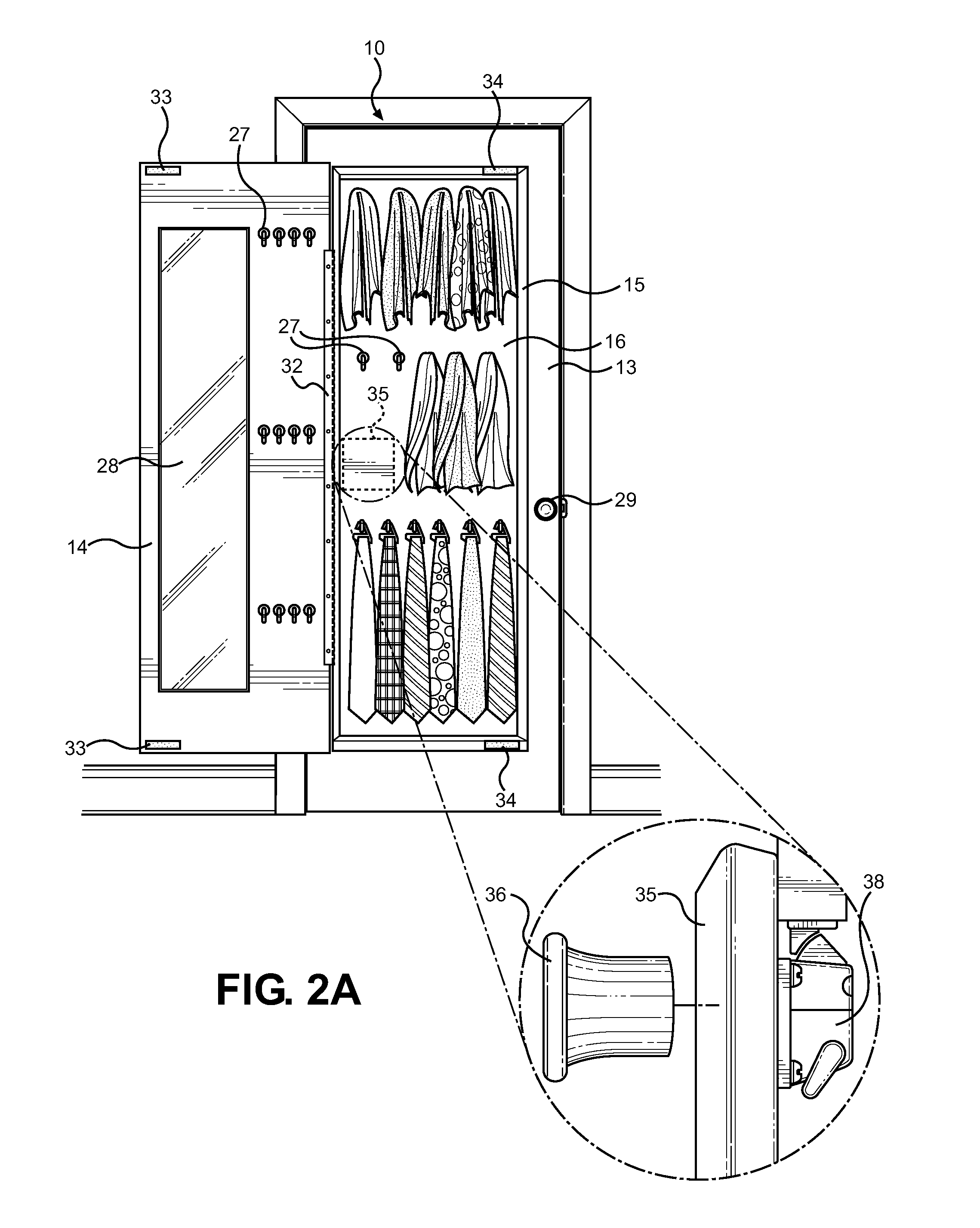
[0031]Reference is made herein to the attached drawings. Like reference numerals are used throughout the drawings to depict like or similar elements of the hollow door storage system of the present invention. For the purposes of presenting a brief and clear description of the present invention, the preferred embodiment will be discussed as used for storing personal items within a door using a hollow door interior, and further providing at least one interior panel with a discreet locking means thereon for controlling access to an interior cavity therein. The figures are intended for representative purposes only and should not be considered to be limiting in any respect.

[0032]Referring now to FIGS. 1 and 4, there is shown the hollow door storage device of the present invention in a fully open position and a view of the hollow door interior 10 with a variety of accessories disposed therein. The device defines a hollow door interior 10 that is disposed within an outer door 13 surface ar...


PUM


Abstract

A storage device mounted within a door frame is disclosed for storage and organization of fashion accessories or similar articles is provided. The device comprises an outer door supported by the door frame, an interior door enclosing a hollow door interior for storage of articles, and at least one interior panel within the hollow door interior to separate an interior cavity therein and limit access thereto via a hidden locking mechanism. The interior panel provides separation of the internal cavity from the hollow door interior, increases surface area of the hollow door interior, and segregates a hidden interior cavity therein. The back wall of the interior cavity also provides a location for further hooks and shelving for storage. The device may be provided within the interior of a larger door, or as a door insert adapted to be incorporated into an existing door.

Description

CROSS REFERENCE TO RELATED APPLICATION[0001]This application is a Continuation in Part of U.S. patent application Ser. No. 13 / 221,946 filed on Aug. 31, 2011, entitled “Fashion Accessory Internal Door Storage Cavity,” now pending, which claims the benefit of U.S. Provisional Application No. 61 / 464,451 filed on Mar. 4, 2011, entitled “The Fashion Accessory Store Door.” The patent application identified above is incorporated here by reference in its entirety to provide continuity of disclosure.BACKGROUND OF THE INVENTION[0002]1. Field of the Invention[0003]The present invention relates to closets and storage areas that may be mounted and located in disguised or hidden locations. More specifically, the present invention pertains to a storage compartment that is housed within an interior door.[0004]Prior to this invention there have been many varieties of doors as well as various cabinet structures. One disadvantage of closets is that they are bulky and require significant floor or wall ...

Claims


Application Information

Patent Timeline
IPC IPC(8): A47B88/22E05G1/04E05B65/00A47B88/80
CPCA47B88/22E05G1/04E05B65/0075E06B7/34A45C11/16
Inventor THOMAS, VICKY RENEE
Owner THOMAS VICKY RENEE
Learn More