Fashion Accessory Internal Door Storage Cavity

a technology for fashion accessories and storage spaces, applied in the field of closets and storage areas, can solve the problems of not optimally structured to maximize the amount of storage space provided, do not provide an improved means of organizing fashion accessories or similar articles, and do not allow for viewing of articles within the storage space, so as to minimize the utilization of floor spa

Inactive Publication Date: 2012-09-06
THOMAS VICKY
View PDF18 Cites 19 Cited by
  • Summary
  • Abstract
  • Description
  • Claims
  • Application Information

AI Technical Summary

Benefits of technology

[0014]In view of the foregoing disadvantages inherent in the known types of door closets now present in the prior art, the present invention provides a new means of storage and organization while minimizing utilized floor space to accomplish these goals.

Problems solved by technology

These devices, however, are not optimally structured to maximize the amount of storage for the space provided, nor do they provide an improved means of organizing fashion accessories or similar articles.
They similarly do not allow for viewing of articles within the storage space itself prior to removal thereof.
The Matselboba device does not extend rearwardly from the closet door, which significantly limits storage space, while its door entry is a door gate that opens using two doors that spread apart to gain access to the hollow interior.
The door closet and closet box both have handles that are similar to that provided in the Matselboba device, which are less than ideal given the additional space that the handles take up within the room.
The storage space is located only against the back wall of the storage container, which does not maximize the space within the storage container.
The devices disclosed in the prior art do not address the need for maximizing the storage space that is available through a storage space within the hollow of a door.

Method used


Image

  • Fashion Accessory Internal Door Storage Cavity
  • Fashion Accessory Internal Door Storage Cavity
  • Fashion Accessory Internal Door Storage Cavity

Examples


Embodiment Construction

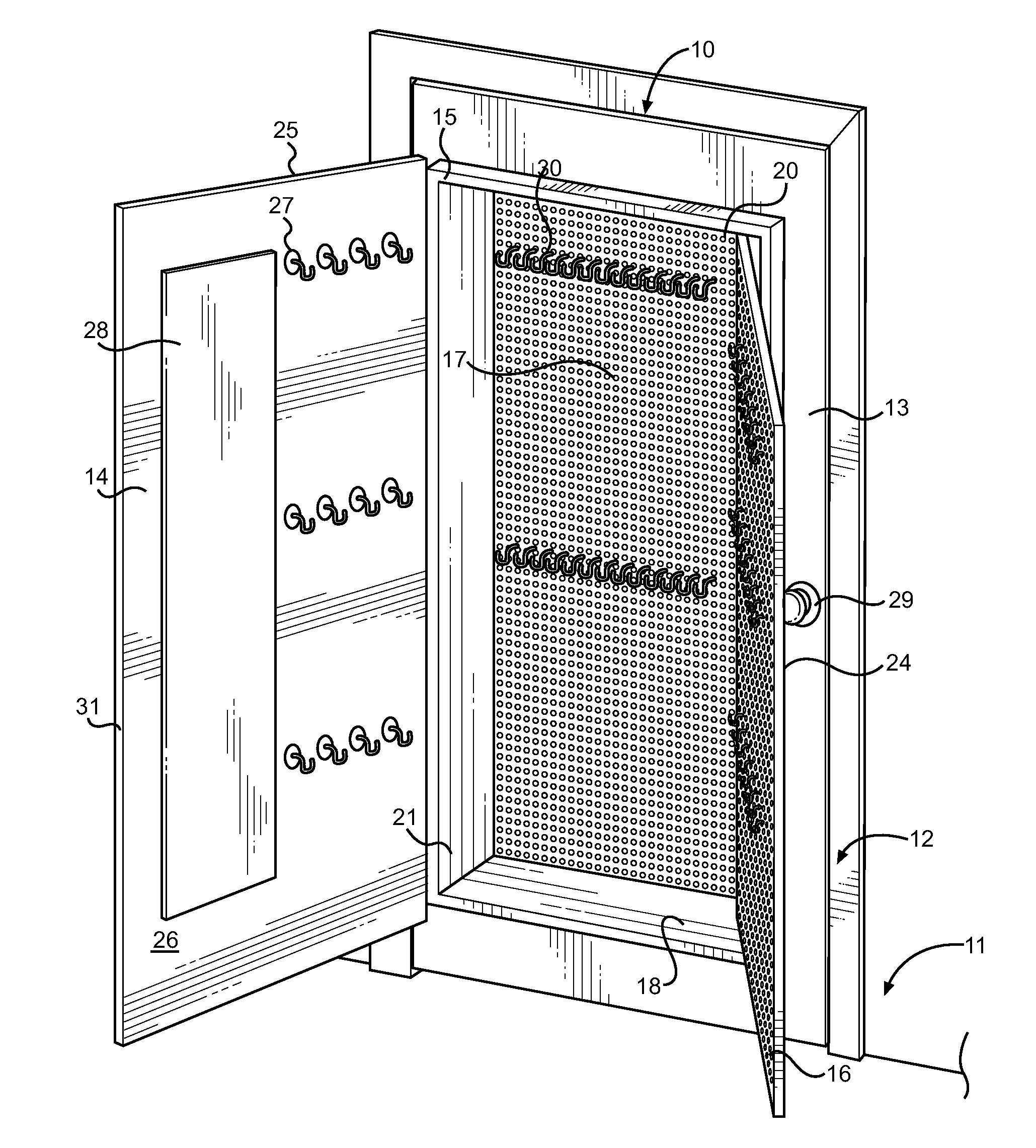
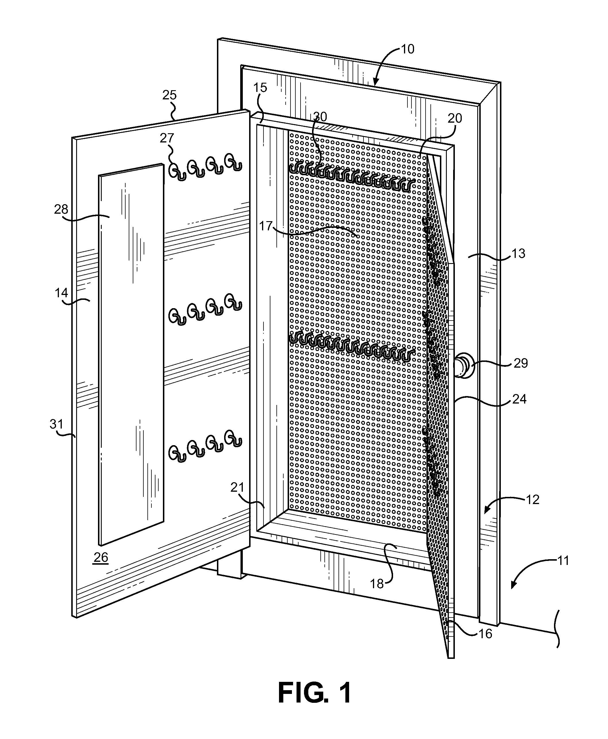
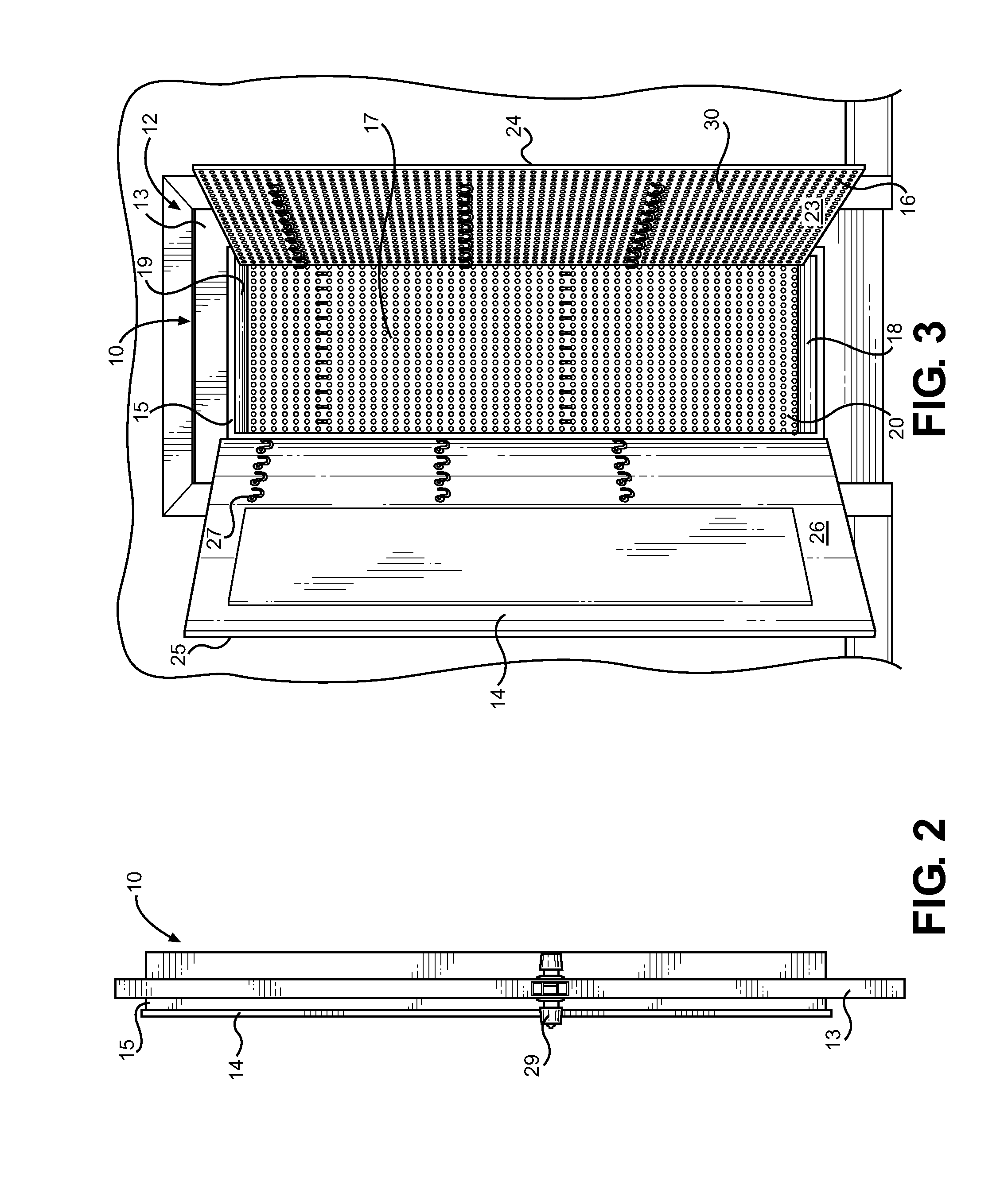
[0026]Referring now to FIGS. 1 and 3, there is shown the hollow door storage device 10 of the present invention in a fully open position. The device defines a structure that fits within an outer door frame 12 along a wall surface 11 to provide a door with an internal storage compartment mounted therein. The device is hingeably mounted to the outer door frame 12 to allow operation as a normal interior door. The device includes a door perimeter handle 29 fixedly mounted to an outer door 13 adjacent to the entrance. An interior door 14 set within the outer door 13 encloses the storage compartment while not in use. The interior door 14 is hingeably mounted to an interior door frame 15 that is set within the outer door 13. The interior door has an outer 25 and interior side 26 as well as an outer 31 and inner edge 32. The interior side of the interior door 26 may have peg board 30 thereattached, along with hooks 27 for holding accessories. A mirror 28 is attached to the interior side of ...


PUM


Abstract

A storage device mounted within a door frame is disclosed for storage and organization of fashion accessories or similar articles. The device comprises a door having an internal cutout, wherein an internal cavity is provided for storage of articles in a condensed space, which can be accessed via a second, cutout door. A full length mirror is mounted to the interior of the second door along with peg board to allow attachment of accessory hooks for hanging items. One or more hinged panels inside of the interior cavity provide separation of the internal cavity and increased surface area to allow attachment of additional hooks or attachment means. The back wall of the interior cavity also provides a location for further hooks and shelving for storage. The device may be provided within the interior of a larger door, or as a door insert adapted to be incorporated into an existing door.

Description

CROSS REFERENCE TO RELATED APPLICATION[0001]This application claims the benefit of U.S. Provisional Application No. 61 / 464,451 filed on Mar. 4, 2011, entitled “The Fashion Accessory Store Door.”BACKGROUND OF THE INVENTION[0002]1. Field of the Invention[0003]The present invention relates to closets and storage areas that may be mounted and located in disguised or hidden locations. More specifically, the present invention pertains to a storage compartment that is housed within an interior door.[0004]Prior to this invention there have been many varieties of doors as well as various cabinet structures. One disadvantage of closets is that they are bulky and require significant floor or wall space. Many families today are choosing to live in smaller dwellings to reduce cost outlays for housing. Such families, along with other types, have a need for improved storage space that does not occupy a large portion of the household livable area.[0005]In the past, a variety of devices have been us...

Claims


Application Information

Patent Timeline
Patent Type & Authority Applications(United States)
IPC IPC(8): A47B46/00
CPCE06B7/34
Inventor THOMAS, VICKY
Owner THOMAS VICKY
Why Eureka
Try Eureka