
Eureka
For R&D, Eureka makes reading and utilizing patents & technical documents easy.
Eureka AIR
Designed for self-driven R&D workflows. Generate viable solutions, solve complex R&D challenges, empower your innovation with AI.

Eureka Materials
Designed for material experts only. Revolutionize your material R&D, from search, analyze, to developing new materials.

TechResearch
Generate reliable direction feasibility study reports for your R&D in just a few steps.

TechSeek
Discover and master advanced knowledge NOW. Basics, ideas, possibilities, all at once.

TechMind
As an expert in R&D Theories, TechMind can generates customized viable solutions instantly.

TechRisk
Analyze your overall solution with one click, know your potential R&D risks in advance.

TechMonitor
Get weekly tech updates, stay abreast of the latest tech innovations and key insights.
Plastic lens barrel and method for manufacturing the same
- Summary
- Abstract
- Description
- Claims
- Application Information
AI Technical Summary
Benefits of technology
Problems solved by technology
Method used
Image

Examples
1st embodiment
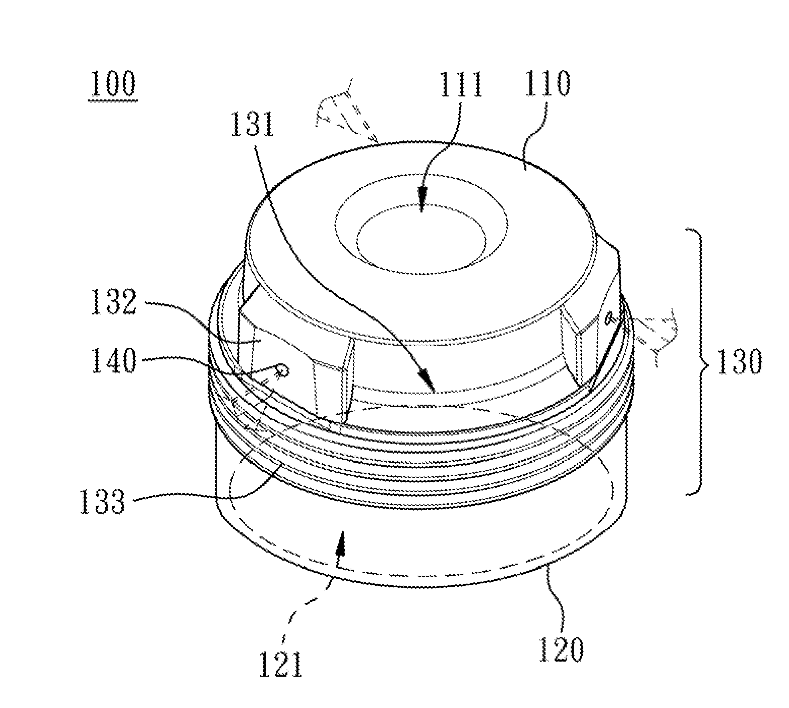
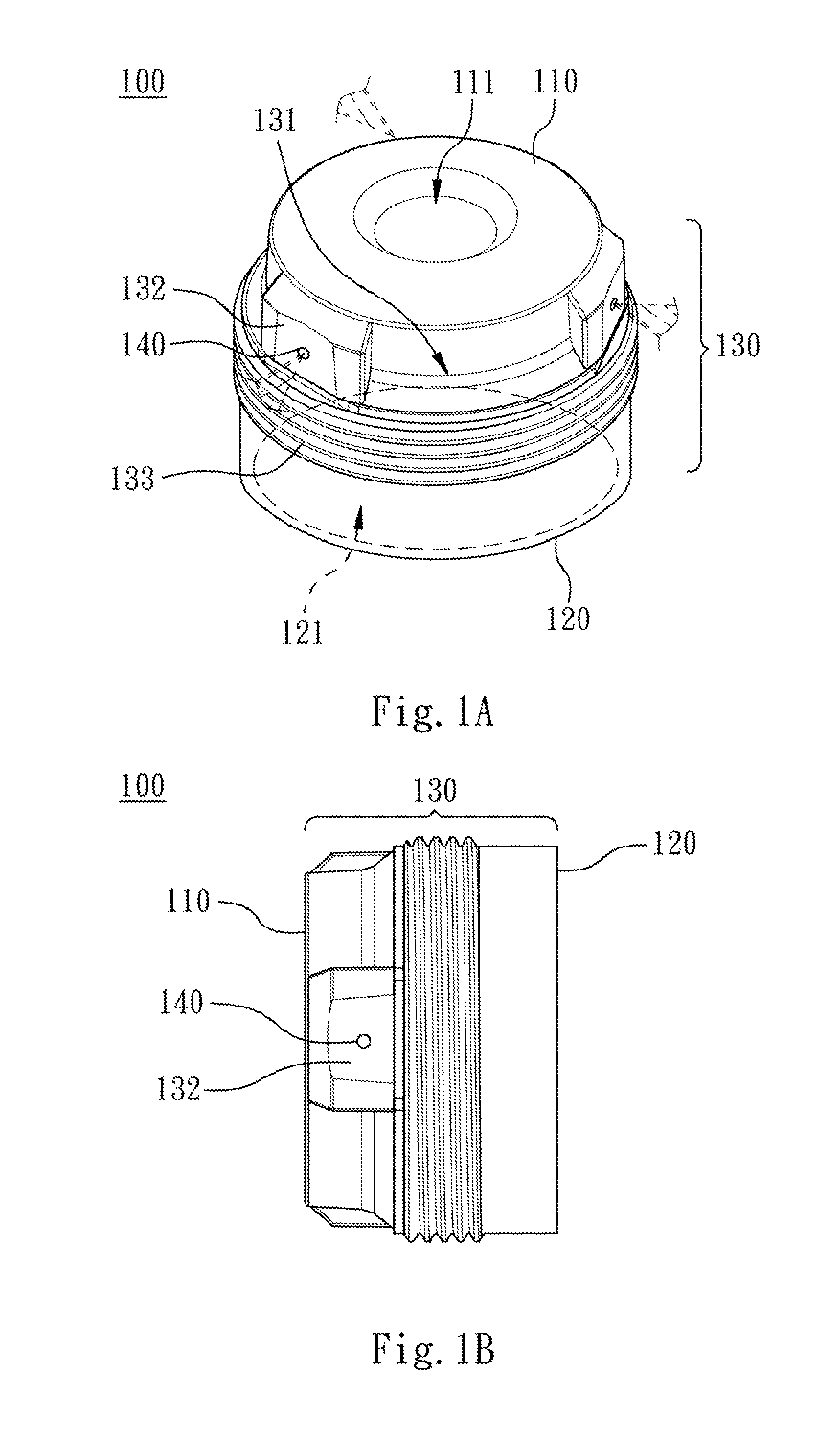
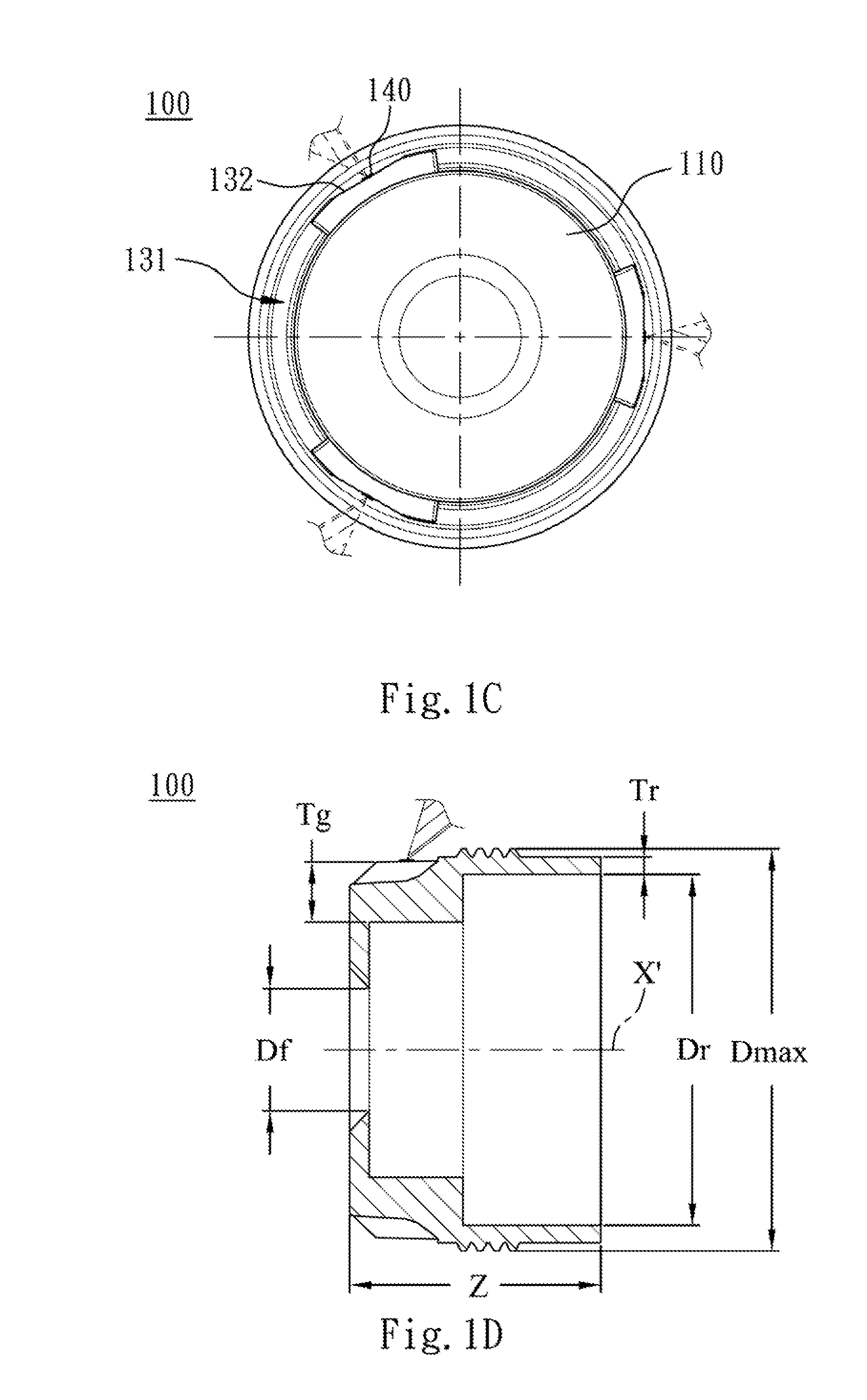
[0058]FIG. 1A is a schematic view of a plastic lens barrel according to the 1st embodiment of the present disclosure. FIG. 1B is a side view of the plastic lens barrel shown in FIG. 1A.
[0059]In FIG. 1A and FIG. 1B, the plastic lens barrel 100 includes a front portion 110, a rear portion 120, a side portion 130, and three gate vestiges 140. The plastic lens barrel 100 is integrally formed. The front portion 110 and the rear portion 120 are located at two ends of the plastic lens barrel 100, respectively. The side portion 130 connects the front portion 110 and the rear portion 120. The gate vestiges 140 are formed on at least one of the front portion 110, the rear portion 120, and the side portion 130. Specifically, the gate vestiges 140 are formed on the side portion 130 and closer to the front portion 110 than to the rear portion 120. The front portion 110 has a front opening 111, and the rear portion 120 has a rear opening 121. The side portion 130 includes three indentations 131, ...
2nd embodiment
[0062]FIG. 2A is a schematic view of a plastic lens barrel according to the 2nd embodiment of the present disclosure. FIG. 2B is a side view of the plastic lens barrel shown in FIG. 2A.
[0063]In FIG. 2A and FIG. 2B, the plastic lens barrel 200 includes a front portion 210, a rear portion 220, a side portion 230, and three gate vestiges 240. The plastic lens barrel 200 is integrally formed. The front portion 210 and the rear portion 220 are located at two ends of the plastic lens barrel 200, respectively. The side portion 230 connects the front portion 210 and the rear portion 220. The gate vestiges 240 are formed on at least one of the front portion 210, the rear portion 220, and the side portion 230. Specifically, the gate vestiges 240 are formed on the side portion 230 and closer to the front portion 210 than to the rear portion 220. The front portion 210 has a front opening 211, and the rear portion 220 has a rear opening 221. The side portion 230 includes six indentations 231, an...
3rd embodiment
[0066]FIG. 3A is a schematic view of a plastic lens barrel according to the 3rd embodiment of the present disclosure. FIG. 3B is a side view of the plastic lens barrel shown in FIG. 3A.
[0067]In FIG. 3A and FIG. 3B, the plastic lens barrel 300 includes a front portion 310, a rear portion 320, a side portion 330, and three gate vestiges 340. The plastic lens barrel 300 is integrally formed. The front portion 310 and the rear portion 320 are located at two ends of the plastic lens barrel 300, respectively. The side portion 330 connects the front portion 310 and the rear portion 320. The gate vestiges 340 are formed on at least one of the front portion 310, the rear portion 320, and the side portion 330. Specifically, the gate vestiges 340 are formed on the side portion 330 and closer to the front portion 310 than to the rear portion 320. The front portion 310 has a front opening 311, and the rear portion 320 has a rear opening 321. The side portion 330 includes six indentations 331, th...
PUM
 Abstract
Description
Claims
Application Information
 - R&D Engineer
- R&D Manager
- IP Professional
- Industry Leading Data Capabilities
- Powerful AI technology
- Patent DNA Extraction
Browse by: Latest US Patents, China's latest patents, Technical Efficacy Thesaurus, Application Domain, Technology Topic, Popular Technical Reports.
© 2024 PatSnap. All rights reserved.Legal|Privacy policy|Modern Slavery Act Transparency Statement|Sitemap|About US| Contact US: help@patsnap.com