Nail polish removal device

a technology for nail polish removal and nail polish, which is applied in the direction of hand devices, packaging foodstuffs, packaged goods, etc., can solve the problem of no longer effective removal of additional nail polish

Inactive Publication Date: 2014-05-15
DOCKERY NETRISA TAKESHA P
View PDF5 Cites 25 Cited by
  • Summary
  • Abstract
  • Description
  • Claims
  • Application Information

AI Technical Summary

Problems solved by technology

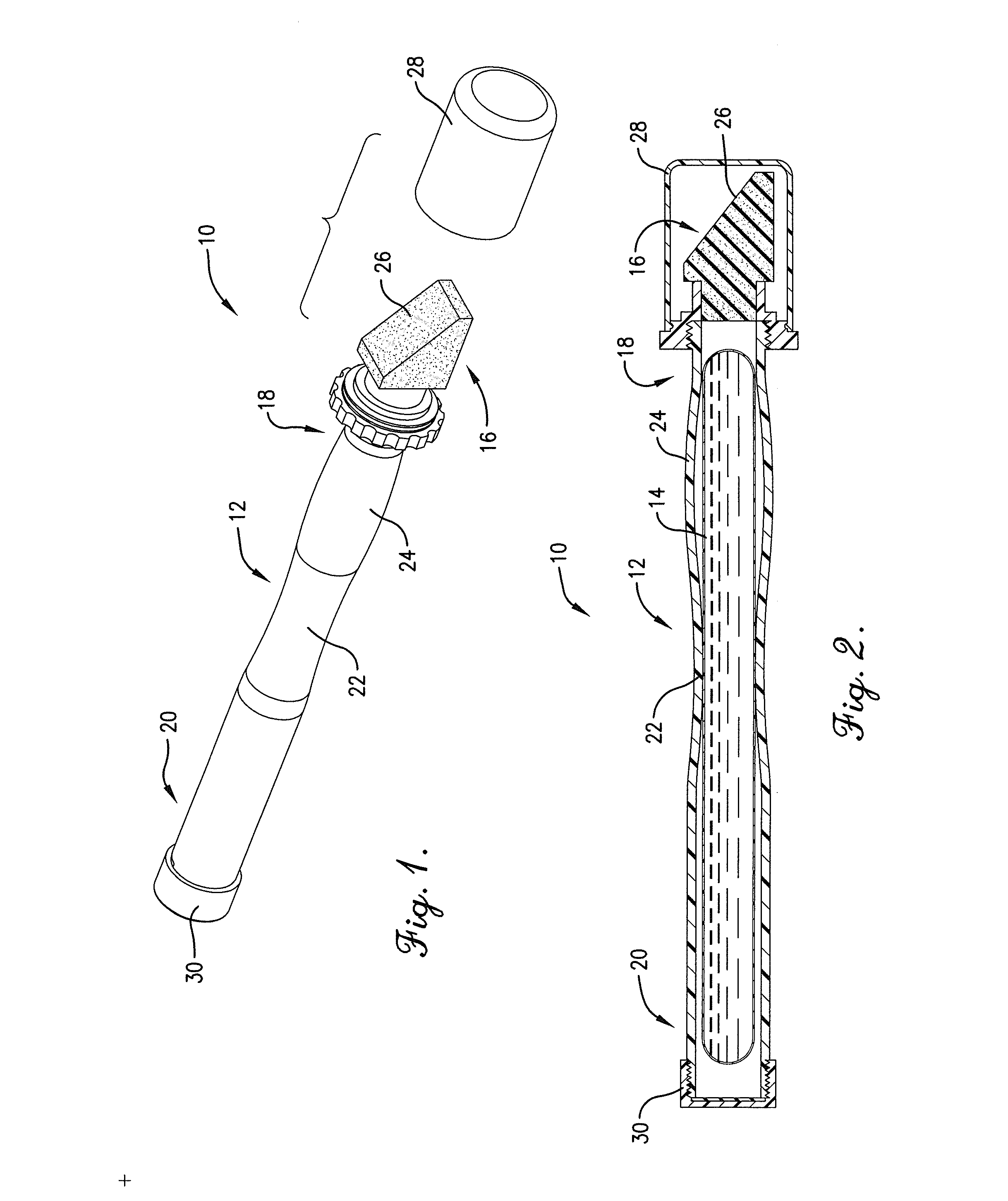
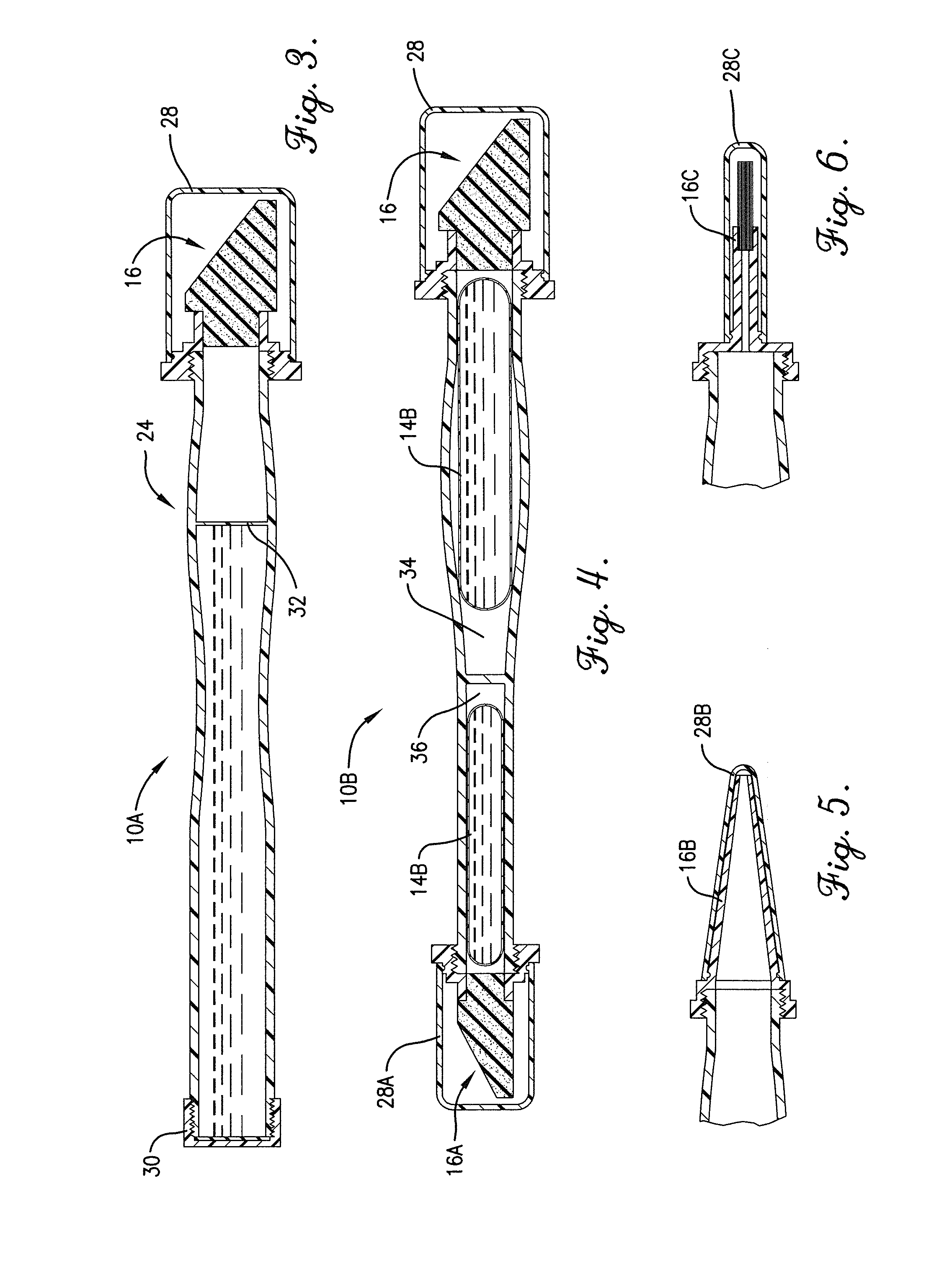
Advantageously, the applicator tip may be removed and replaced with a new applicator tip once it is saturated or coated with nail polish and no longer effective at removing additional nail polish.

Method used


Image

  • Nail polish removal device
  • Nail polish removal device
  • Nail polish removal device

Examples


Embodiment Construction

[0022]The following detailed description of embodiments of the invention references the accompanying drawings. The embodiments are intended to describe aspects of the invention in sufficient detail to enable those skilled in the art to practice the invention. Other embodiments can be utilized and changes can be made without departing from the scope of the claims. The following detailed description is, therefore, not to be taken in a limiting sense. The scope of the present invention is defined only by the appended claims, along with the full scope of equivalents to which such claims are entitled.

[0023]In this description, references to “one embodiment”, “an embodiment”, or “embodiments” mean that the feature or features being referred to are included in at least one embodiment of the technology. Separate references to “one embodiment”, “an embodiment”, or “embodiments” in this description do not necessarily refer to the same embodiment and are also not mutually exclusive unless so s...


PUM


Abstract

A nail polish removal device includes a hollow applicator handle and an applicator tip. The applicator handle has an applicator end and an opposite end and releasably contains a nail solution. The applicator tip is removably attached to the applicator end of the applicator handle. The nail solution saturates or passes through the applicator tip when released from the applicator handle.

Description

BACKGROUND[0001]It is often desirable to remove cosmetic nail polish from fingernails and toenails, such as, for example, prior to applying a new cosmetic finish. Two popular nail polish removal systems are bottle-based systems and dipping jar-based systems. Bottle-based nail polish removal systems typically include a multiple-use bottle containing a relatively large quantity of a nail polish removal solution sufficient for numerous applications. The bottle opens at one end and must be properly secured with a cap to prevent the solution from spilling. In use, the solution must be controllably poured from the bottle onto a suitable material, such as a cotton ball or a cloth rag. Once the material is saturated with the nail polish removal solution, the user applies the material to a polished nail in order to remove the nail polish therefrom. This procedure undesirably exposes the user's fingers and nails to the solution, often resulting in removal of nail polish from nails not intende...

Claims


Application Information

Patent Timeline
Patent Type & Authority Applications(United States)
IPC IPC(8): A45D29/00
CPCA45D29/007A45D34/04A45D34/06A45D40/24A45D2200/1009A45D2200/1018
Inventor DOCKERY, NETRISA TAKESHA P.
Owner DOCKERY NETRISA TAKESHA P
Why Eureka
Try Eureka