Display apparatus and control method for saving power thereof

Active Publication Date: 2014-05-22
SAMSUNG DISPLAY CO LTD
View PDF1 Cites 6 Cited by
  • Summary
  • Abstract
  • Description
  • Claims
  • Application Information

AI Technical Summary

Benefits of technology

The present invention provides a display device and method for controlling the brightness of a display unit to save power. The device or method includes a luminance calculation unit and a luminance control unit. The luminance calculation unit calculates a second luminance based on the current luminance of the display unit and a constant determined by Weber's law. The luminance control unit then changes the luminance of the display unit to the second luminance to achieve the desired brightness difference. This technology ensures minimal brightness differences for users, improving the overall energy efficiency of the display device.

Problems solved by technology

A display device consumes power mostly for screen output.
As image quality is improved and a screen size is increased, power consumption increases.
When there is a great amount of central processing unit (CPU) operations or graphic processing and calculation operations, power consumption also increases.
Use of a communication service also increases power consumption.
However, when the power saving mode is set, the user recognizes a change in a display state and thus may feel that it is unnatural.

Method used


Image

  • Display apparatus and control method for saving power thereof
  • Display apparatus and control method for saving power thereof
  • Display apparatus and control method for saving power thereof

Examples


first embodiment

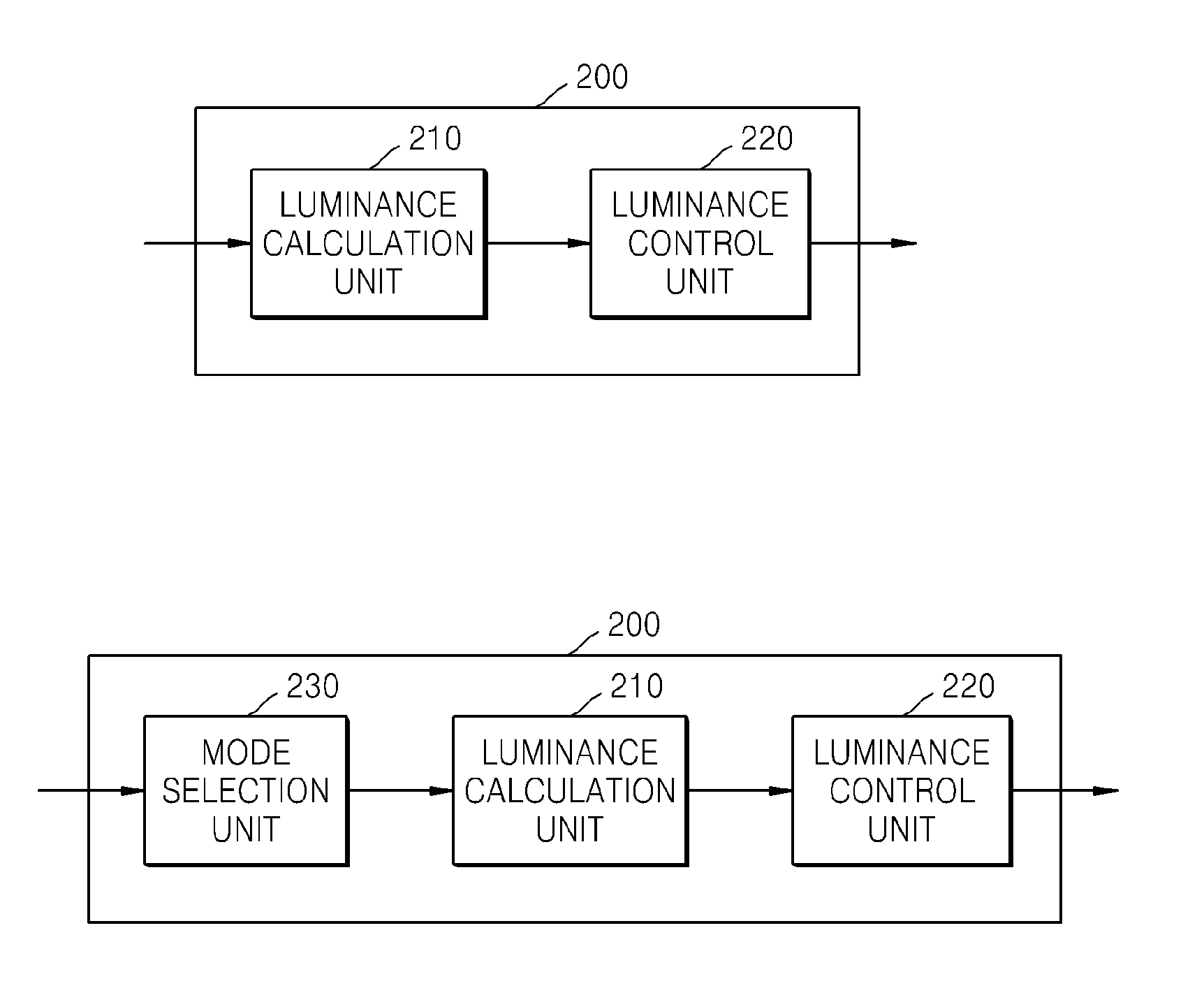
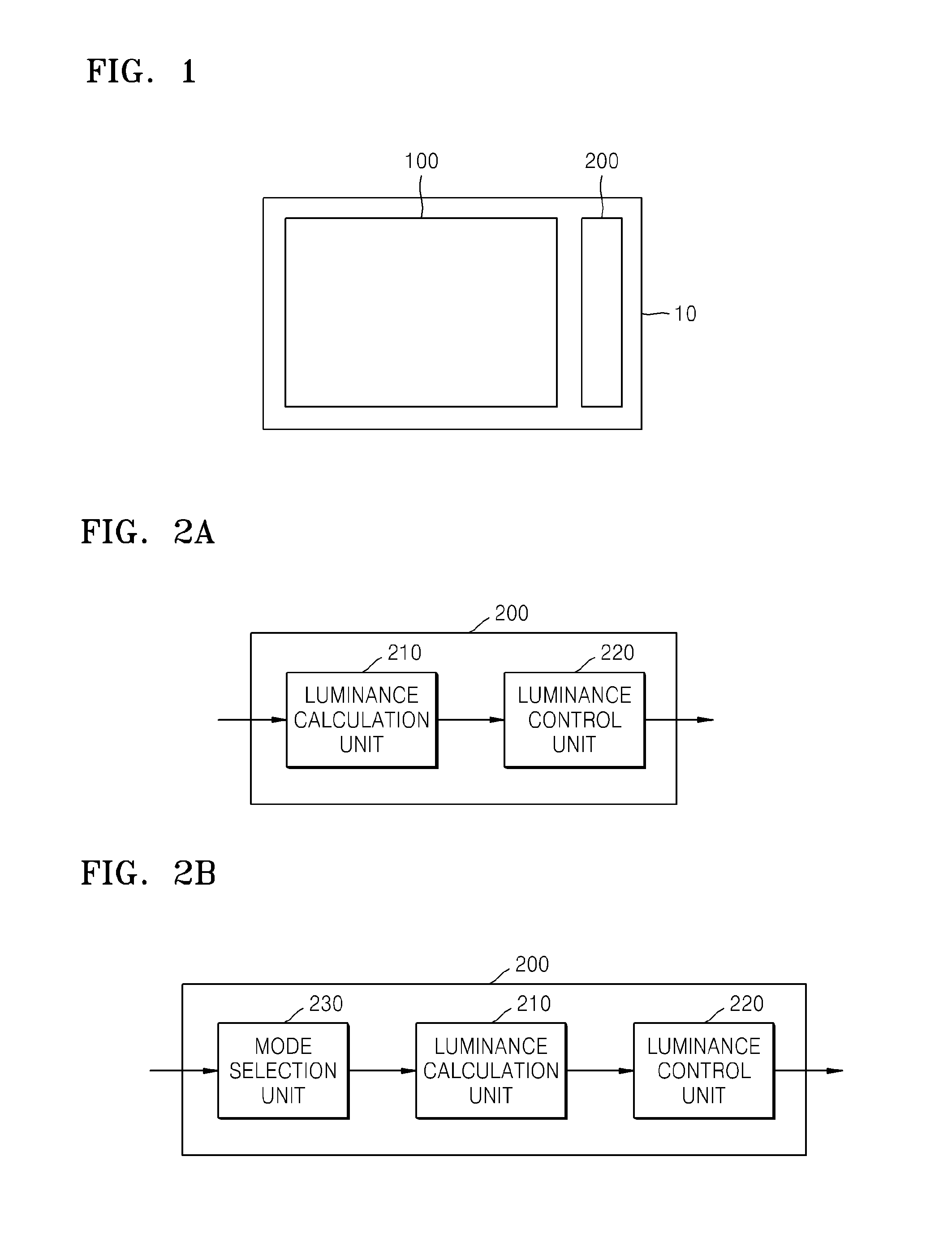
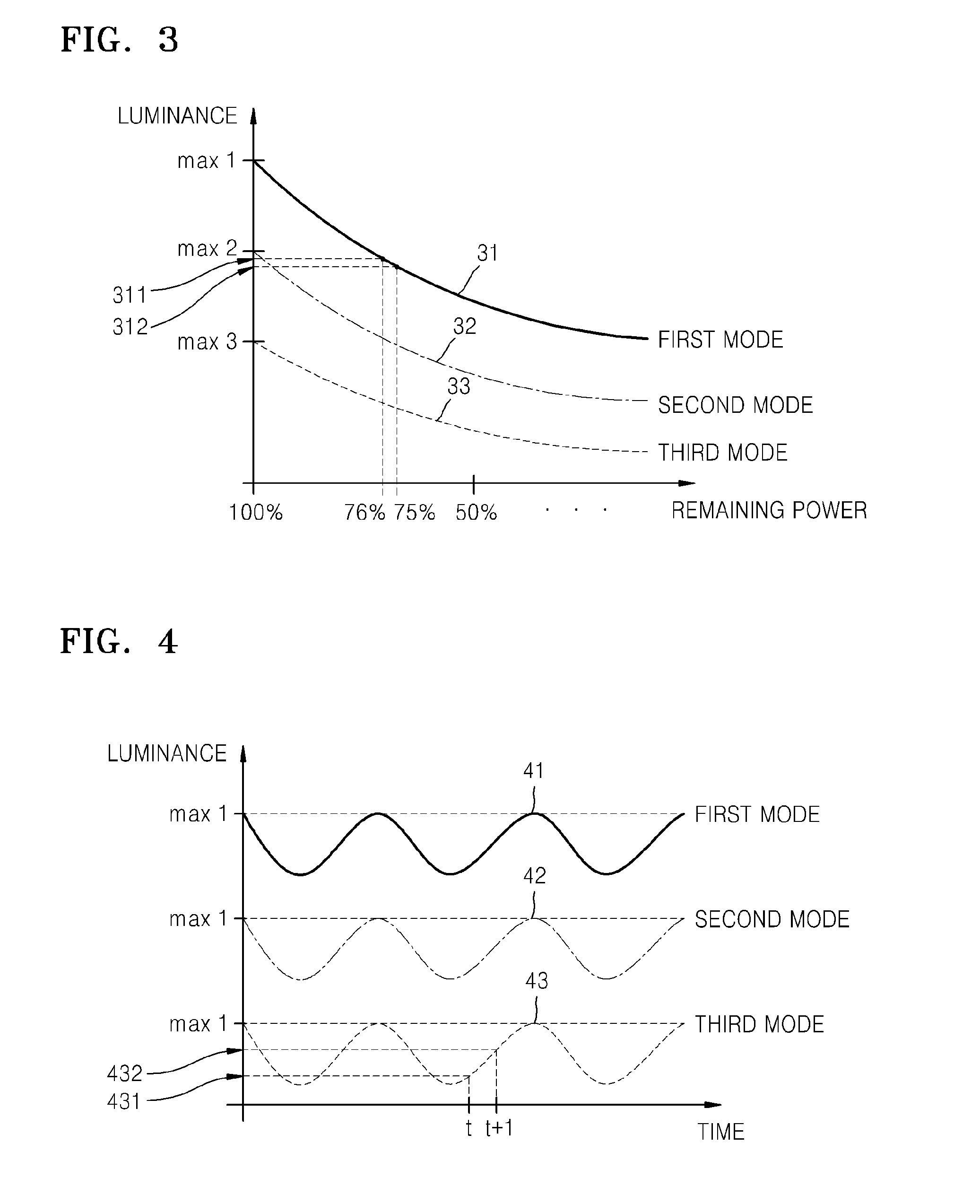
[0040]According to an embodiment of the present invention, maximal luminance corresponding to each mode may be luminance obtained when the remaining power of the display device 10 is 100%. Hereinafter, the luminance obtained when the remaining power of the display device 10 is 100% is referred to as initial luminance. Accordingly, the plurality of modes may differently set the maximal luminance of the display unit 100.

[0041]According to an embodiment of the present invention, the second luminance may have a smaller value than that of the first luminance. Accordingly, the luminance of the display unit 100 may be gradually decreased as a result of control by the control unit 200, and the initial luminance set according to each mode may be set to the maximal luminance so that the luminance is gradually decreased from the maximal luminance.

[0042]For instance, the luminance of the display unit 100 may be gradually decreased as a result of control by the control unit 200 according to the ...

second embodiment

[0053]According to another embodiment of the present invention, the luminance of the display unit 100 may periodically alternate between increasing and decreasing according to the remaining power of the display device 10 or according to a time interval. Maximal luminance corresponding to a mode selected by the mode selection unit 230 may be maximal luminance obtained when the luminance of the display unit 100 periodically alternates. Accordingly, the second luminance of the display unit 100 may be lower than or higher than the first luminance.

[0054]The luminance calculation unit 210 may calculate the second luminance considering the first luminance and the constant K determined according to Weber's law so that the luminance of the display unit 100 periodically alternates within a range not exceeding the maximal luminance selected by the mode selection unit 230. The luminance control unit 220 may change the luminance of the display unit 100 according to the second luminance selected ...


PUM


Abstract

In a method and a device for controlling luminance of a display unit to save power of a display device including the display unit for displaying on a screen, the method includes: calculating a second luminance to which the luminance of the display unit is to be changed considering a first luminance that is a current luminance of the display unit and a constant K determined according to Weber's law; and changing the luminance of the display unit to the second luminance.

Description

CLAIM OF PRIORITY[0001]This application makes reference to, incorporates into this specification the entire contents of, and claims all benefits accruing under 35 U.S.C. §119 from an application earlier filed in the Korean Intellectual Property Office filed on Nov. 19, 2012 and there duly assigned Serial No. 10-2012-0131116.BACKGROUND OF THE INVENTION[0002]1. Field of the Invention[0003]The present invention relates to a power saving method and device for a display device, and more particularly to a display device for controlling the brightness of a display unit based on a minimal brightness difference recognizable by a user, and a method of controlling the display device.[0004]2. Description of the Related Art[0005]A display device consumes power mostly for screen output. As image quality is improved and a screen size is increased, power consumption increases. When there is a great amount of central processing unit (CPU) operations or graphic processing and calculation operations, ...

Claims


Application Information

Patent Timeline
IPC IPC(8): G09G3/22
CPCG09G3/20G09G5/00G09G2320/0626G09G2330/021G06F1/32G09G5/10G09G3/22
Inventor CHOI, BYEONG-HWALEE, SEUNG-BAE
Owner SAMSUNG DISPLAY CO LTD
Why Eureka
Try Eureka