Microsurgical instrument handle

a microsurgical and handle technology, applied in the field of medical devices, can solve the problems of difficult manipulation of the surgical utility control mechanism without unintentional movement, difficulty for surgeons to control and difficulty in manipulating the surgical utility control mechanism

Inactive Publication Date: 2014-05-22
KATALYST SURGICAL
View PDF10 Cites 34 Cited by
  • Summary
  • Abstract
  • Description
  • Claims
  • Application Information

AI Technical Summary

Benefits of technology

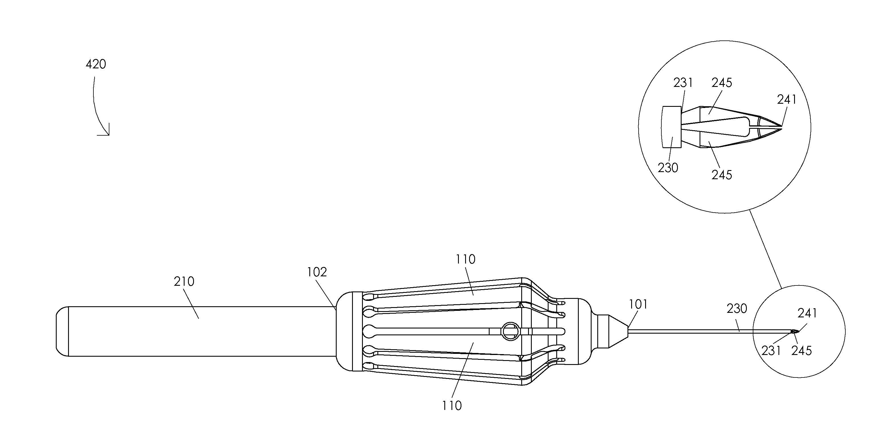
[0005]The present disclosure presents a microsurgical instrument handle. In one or more embodiments, a microsurgical instrument handle may comprise an actuation structure having an actuation structure distal end and an actuation structure proximal end, a plurality of actuation arms of the actuation structure, and a handle base having a handle base proximal end and a handle base distal end. Illustratively, each actuation arm of the plurality of actuation arms may comprise an extension joint. In one or more embodiments, a compression of the actuation structure may be configured to extend the actuation structure distal end relative to the actuation structure proximal end. Illustratively, a decompression the actuation structure may be configured to retract the actuation structure distal end relative to the actuation structure proximal end.

Problems solved by technology

Sometimes a surgeon may require a surgical utility that may not be easily controlled close to a particular surgical site, e.g., closing forceps jaws inside of an eye.
Additionally, if a surgical utility control mechanism requires a surgeon to apply a significant amount of force to a portion of a surgical instrument, then it may be difficult for the surgeon to manipulate the surgical utility control mechanism without unintentionally moving a portion of the surgical instrument.
However, it is important that some effort is required to manipulate a surgical utility control mechanism of a surgical instrument.
For example, if manipulation of a surgical utility control mechanism only requires a surgeon to apply a very small force to a portion of a surgical instrument, then it may be possible for the surgeon to unintentionally manipulate a surgical utility control mechanism during a surgical procedure.

Method used


Image

  • Microsurgical instrument handle
  • Microsurgical instrument handle
  • Microsurgical instrument handle

Examples


Embodiment Construction

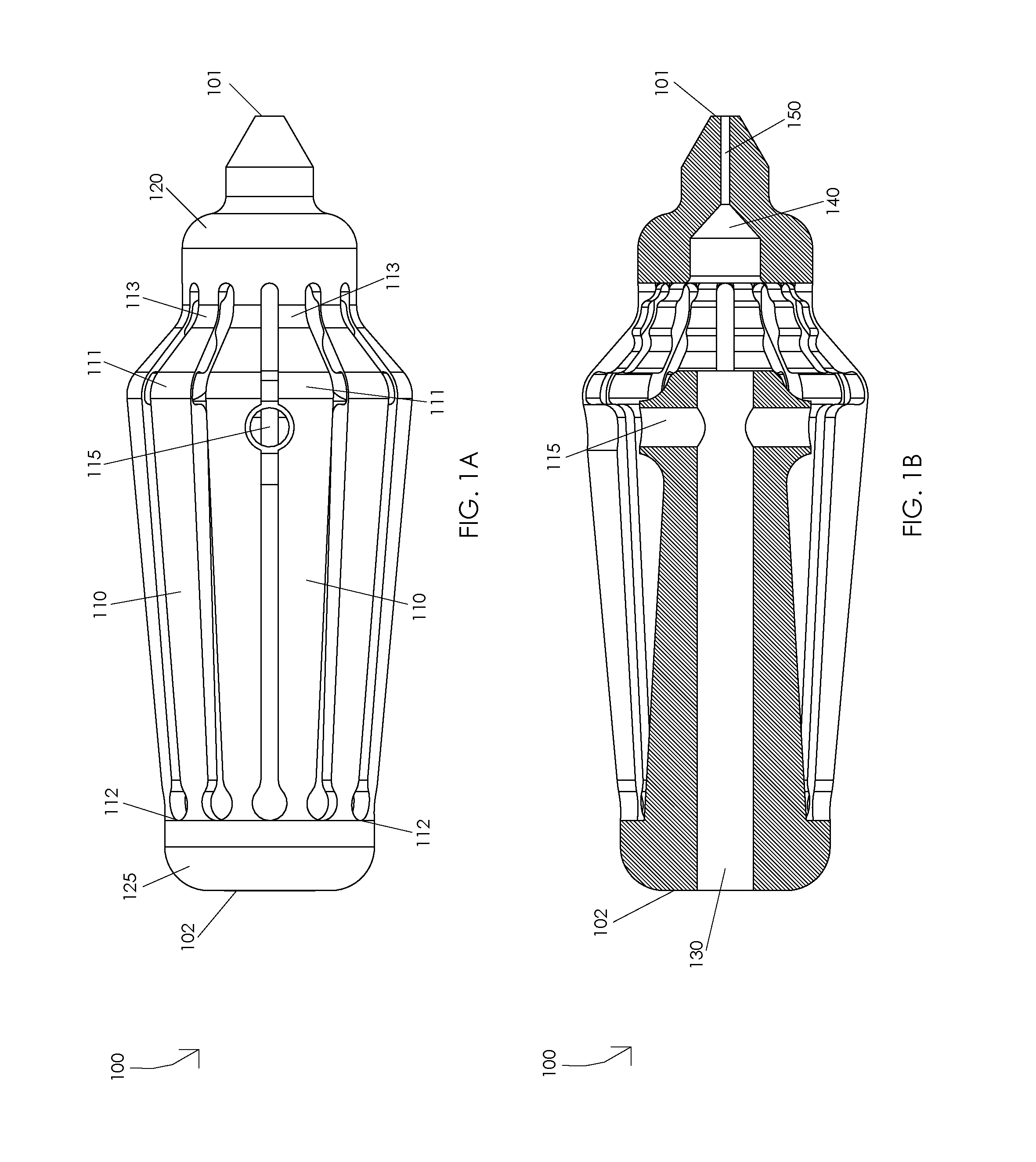
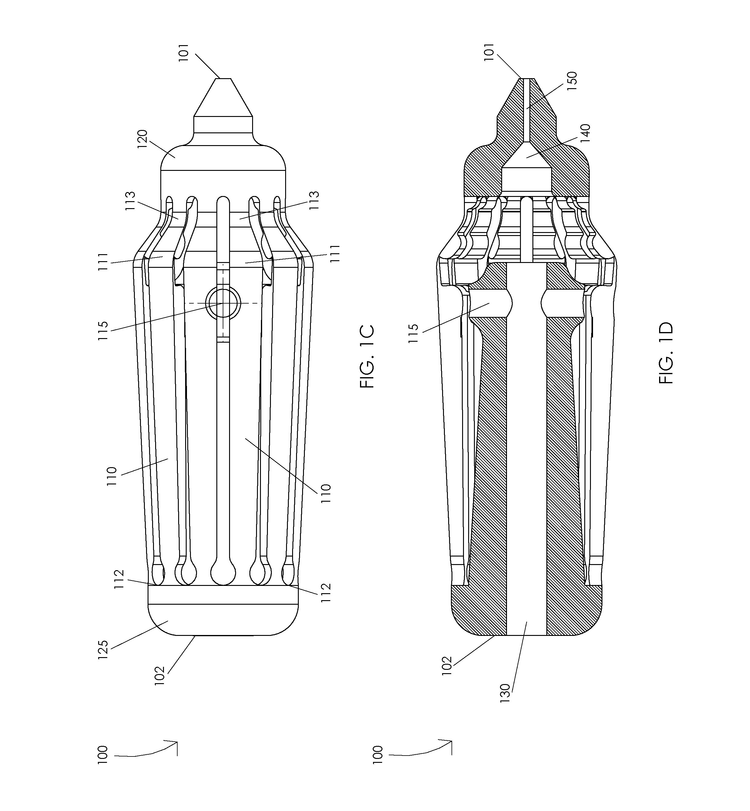
[0011]FIGS. 1A, 1B, 1C, and 1D are schematic diagrams illustrating an actuation structure 100. FIG. 1A illustrates a top view of a decompressed actuation structure 100. Illustratively, actuation structure 100 may comprise an actuation structure distal end 101 and an actuation structure proximal end 102, a plurality of actuation arms 110, a fixation mechanism housing 115, an actuation arm distal interface 120, and an actuation arm proximal interface 125. In one or more embodiments, each actuation arm 110 of a plurality of actuation arms 110 may comprise an extension joint 111, a proximal extension hinge 112, and a distal extension hinge 113. Illustratively, actuation structure distal end 101 may extend a decompressed distance from actuation structure proximal end 102, e.g., when actuation structure 100 comprises a decompressed actuation structure 100. In one or more embodiments, a decompressed distance may be in a range of 1.6 to 3.0 inches, e.g., a decompressed distance may be 2.25 ...


PUM


Abstract

A microsurgical instrument handle may include an actuation structure having an actuation structure distal end and an actuation structure proximal end, a plurality of actuation arms of the actuation structure, and a handle base having a handle base proximal end and a handle base distal end. Each actuation arm of the plurality of actuation arms may include an extension joint. A compression of the actuation structure may be configured to extend the actuation structure distal end relative to the actuation structure proximal end. A decompression the actuation structure may be configured to retract the actuation structure distal end relative to the actuation structure proximal end.

Description

CROSS-REFERENCE TO RELATED APPLICATIONS[0001]This Application claims the benefit of U.S. Provisional Application No. 61 / 727,901, filed Nov. 19, 2012.FIELD OF THE INVENTION[0002]The present disclosure relates to a medical device, and, more particularly, to a surgical instrument.BACKGROUND OF THE INVENTION[0003]A variety of surgical procedures are performed through a very small surgical incision in a particular tissue. Reducing the size of a surgical incision during a surgical procedure generally reduces the amount of trauma to the surgical site and generally facilitates faster wound healing. In order to perform surgical procedures through a very small surgical incision, a surgeon may require specialized surgical instruments configured to fit through the very small surgical incision and provide the surgeon with a surgical utility. Sometimes a surgeon may require a surgical utility that may not be easily controlled close to a particular surgical site, e.g., closing forceps jaws inside ...

Claims


Application Information

Patent Timeline
Patent Type & Authority Applications(United States)
IPC IPC(8): A61B17/29A61B17/3201A61B17/00
CPCA61B17/30A61B2017/2918A61B2017/305A61B17/2909A61B17/3201
Inventor SCHELLER, GREGG D.ZEID, MATTHEW N.
Owner KATALYST SURGICAL
Why Eureka
Try Eureka