Elastic tube alignment system for precisely locating components

a technology elastic tubes, applied in the field of precisely locating components, can solve the problems of poor fit, considerable float, unbalanced appearance, etc., and achieve the effect of increasing height, smooth and easy operation, and facilitating initial entry

Inactive Publication Date: 2014-06-12
GM GLOBAL TECH OPERATIONS LLC
View PDF4 Cites 15 Cited by
  • Summary
  • Abstract
  • Description
  • Claims
  • Application Information

AI Technical Summary

Benefits of technology

The present invention is an elastic tube alignment system that uses elastic averaging to align components. The system includes elastic tube alignment features on one component and corresponding aperture alignment features on another component. The elastic tube alignment features have a larger diameter than the aperture alignment features. When the two components are mated together, the elastic tube alignment features deform and align with the aperture alignment features, resulting in a precise alignment and a smooth mating process. The elastic tube alignment features and the aperture alignment features can be elastically deformed and reversed. The system is suitable for various attachment methods, such as threaded fasteners, heat staking, sonic welding, push nuts, clips, etc. The invention provides a precise alignment and a smooth mating process between components, resulting in a high-quality finish.

Problems solved by technology

As a result, there can occur significant positional variation as between the mated first and second components which contributes to the presence of undesirably large and varying gaps and otherwise poor fit therebetween.
Problematically, however, there is considerable float as between the elongated rib in relation to the narrow slot and as between the pronged stud and the wide slot.
When the threaded fasteners are screwed in, any misfit of alignment becomes manifest, and the visible joint between the two components may be irregular, have too large a gap, be unbalanced in appearance, etc., in any event the misfit of alignment rendering the fit unacceptable for a Class A finish.

Method used


Image

  • Elastic tube alignment system for precisely locating components
  • Elastic tube alignment system for precisely locating components
  • Elastic tube alignment system for precisely locating components

Examples


Embodiment Construction

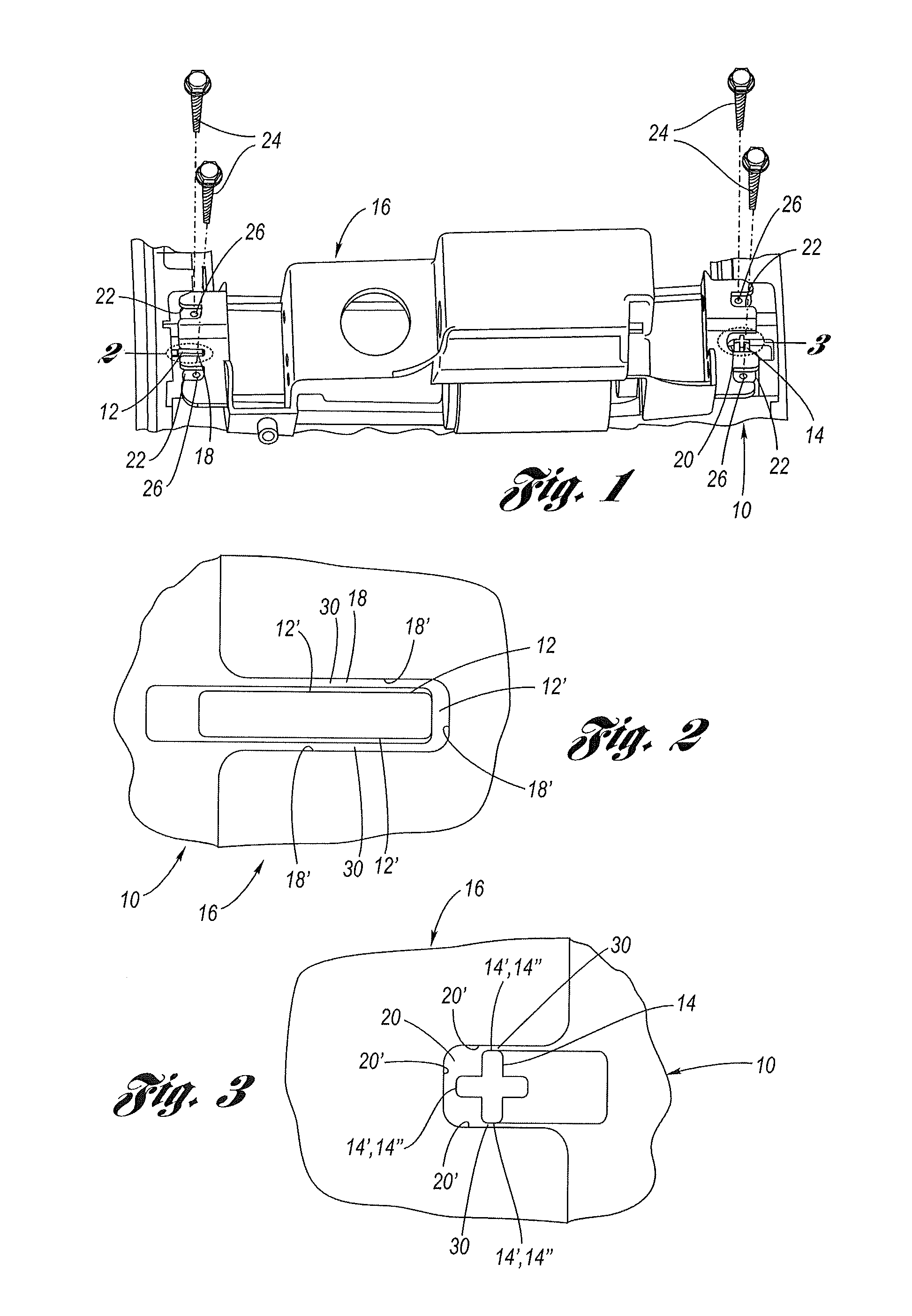
[0032]Referring now to the Drawing, FIGS. 4 through 14 depict various examples of the structure and function of the elastic tube alignment system according to the present invention.

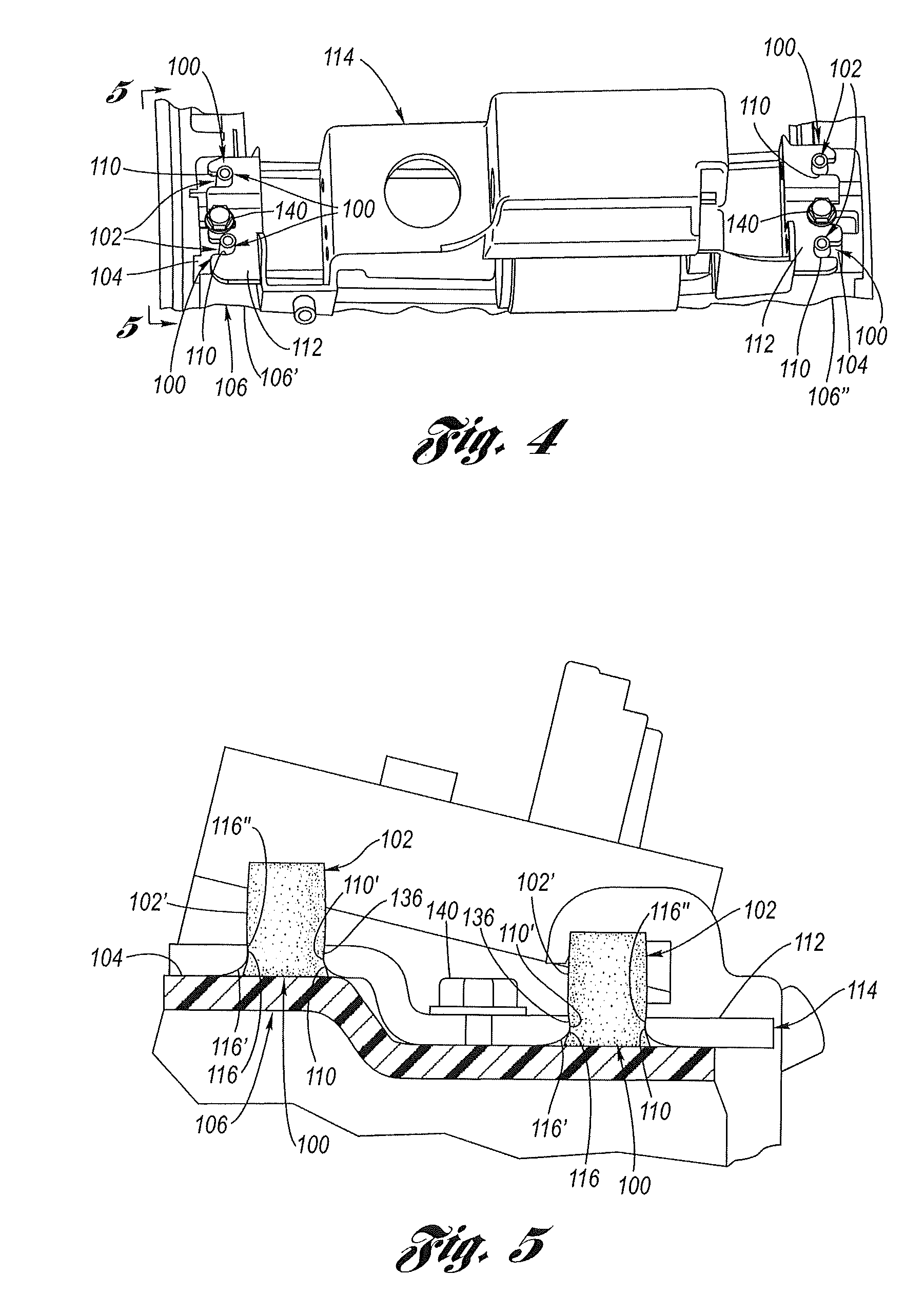
[0033]Referring firstly to FIGS. 4 through 8, the general principles of the elastic tube alignment system 100 according to the present invention will be detailed, wherein the elastic tube alignment system operates on the principle of elastic averaging.

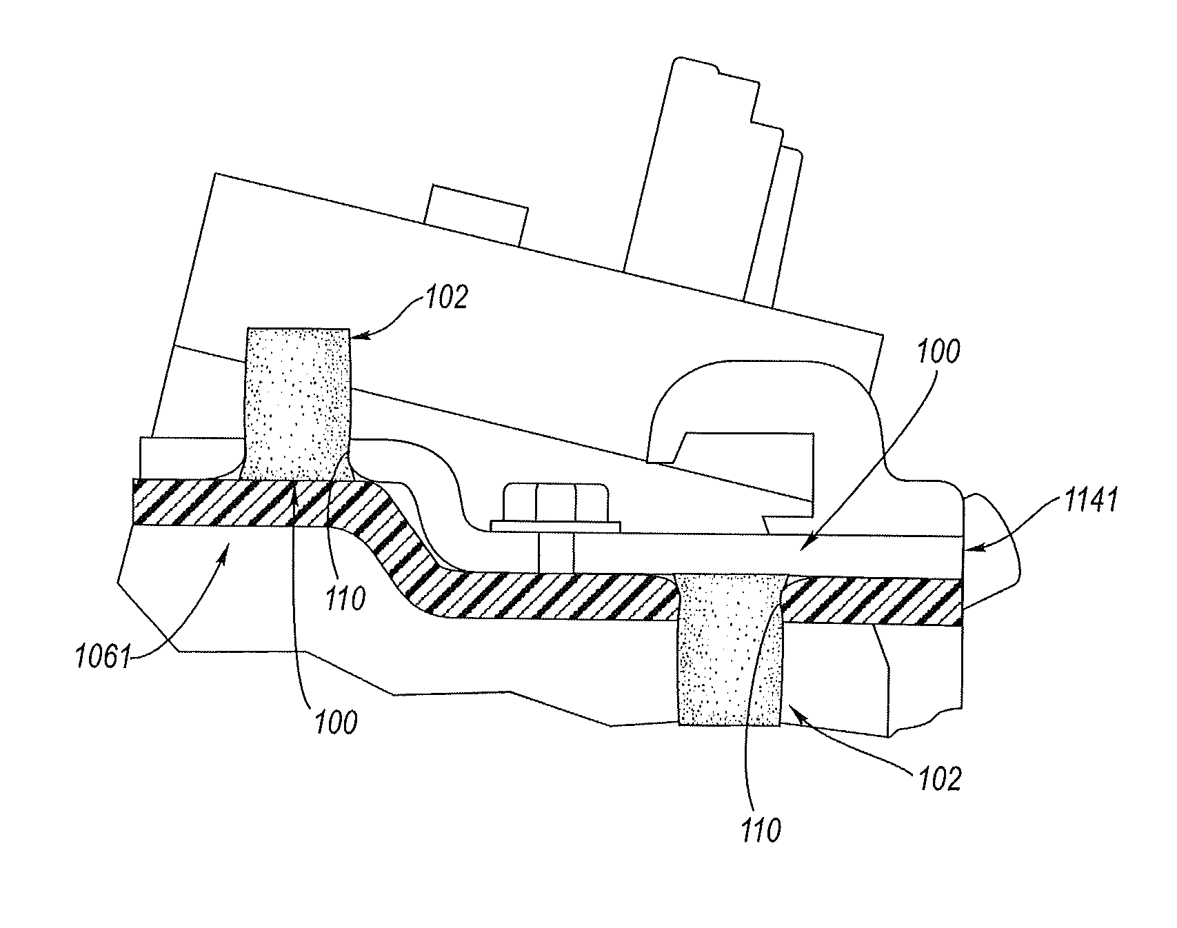
[0034]A plurality of mutually separated elastic tube alignment features (serving as male alignment features) 102 (hereinafter referred to simply as “elastic tubes”) are disposed on a first surface 104 of a first component 106. As best shown at FIG. 5, the elastic tubes 102 are upstanding in normal relation to the first surface 104, wherein a mutually separated pair of elastic tubes is disposed at both a left end 106′ and a right end 106″ of the first component 106. Each of the elastic tubes 102 is tubular in shape, having a tube wall 102′. Preferably, the tu...


PUM


Abstract

An elastic tube alignment system for the mating of components utilizing the principle of elastic averaging. A plurality of geometrically separated elastic tube (male) alignment features are disposed on a first component, while a plurality of one-to-one corresponding aperture (female) alignment features are provided on a second component. During the mating of the components, each elastic tube and its respective aperture provide elastic deformation, which, on average, precisely aligns the components.

Description

CROSS REFERENCE TO RELATED APPLICATIONS[0001]This application claims the benefit U.S. application Ser. No. 13 / 187,675 filed Jul. 21, 2011 and published as U.S. Pub. No. 2013 / 0019455, the contents of which are incorporated herein by reference thereto.FIELD OF THE INVENTION[0002]The present invention relates to location features for aligning of components during a mating operation. More particularly, the present invention relates to a plurality of mutually spaced apart elastic tube alignment features of a first component which elastically deform on average when mated to receiving aperture alignment features of a second component to thereby precisely align the first and second components during a mating operation.BACKGROUND OF THE INVENTION[0003]Currently, components which are to be mated together in a manufacturing process are mutually located with respect to each other by 2-way and / or 4-way male alignment features, typically upstanding bosses, which are received into corresponding fe...

Claims


Application Information

Patent Timeline
Patent Type & Authority Applications(United States)
IPC IPC(8): B62D27/04B25B27/00
CPCB62D27/04B25B27/0035B25B27/00B25B27/14F16B19/002Y10T24/44009Y10T29/49954Y10T24/42Y10T29/53996Y10T29/49899Y10T29/4987B23P11/00
Inventor MORRIS, STEVEN E.
Owner GM GLOBAL TECH OPERATIONS LLC
Why Eureka
Try Eureka