Optical pickup device capable of handling a plurality of laser light beams having different wavelengths

a laser light beam and optical pickup technology, applied in the field of optical pickup devices, can solve the problems of reducing the power affecting the quality and increasing the outer size and the number of parts, so as to achieve high laser power and prevent the reduction of laser light beams.

Inactive Publication Date: 2010-08-24
SANYO ELECTRIC CO LTD
View PDF25 Cites 0 Cited by
  • Summary
  • Abstract
  • Description
  • Claims
  • Application Information

AI Technical Summary

Benefits of technology

[0014]An object of the present invention is to provide an optical pickup device whose optical axis adjustment can be smoothly performed while an increase in cost is suppressed and whose optical axis correction can be accurately performed even in the case where a variation in arrangement gap between laser elements is caused.
[0020]According to the present invention, low cost diffraction gratings are used as the optical elements for optical axis adjustment, so that an increase in cost of the optical pickup device can be suppressed. In addition, the diffraction gratings are separately prepared for laser light beams to be subjected to the optical axis adjustment. Therefore, even when a variation in arrangement gap between the laser elements is caused, the position of a corresponding diffraction grating can be adjusted in an optical axis direction to align the optical axis of the laser light beam with a reference optical axis. Thus, according to the present invention, the optical axis adjustment of the laser light beam can be easily and smoothly performed while an increase in cost of the optical pickup device is suppressed.
[0023]When the laser light beams having the wavelengths of λ1, λ2, and λ3 are the blue-violet laser light beam, the red laser light beam, and the infrared laser light beam, respectively, it is possible to improve the diffraction efficiency of the blue-violet laser light beam. Therefore, the power of the blue-violet laser light beam whose emitting power is small at present can be prevented from being reduced by diffraction.
[0026]When the diffraction grating is located on the second optical path, aberration of corresponding laser light beam is suppressed from being produced on the photo detector because the laser light beam is subjected to the optical axis adjustment before it is incident on the photo detector. At this time, the laser light beam is not subjected to the optical axis adjustment before it is incident on the recording medium, so that aberration is produced on the recording medium. On the other hand, power of the laser light beam is prevented from being reduced by diffraction. Thus, high laser power can be maintained on the recording medium.

Problems solved by technology

However, when such the arrangement is employed, spaces for locating the respective semiconductor lasers and optical elements for guiding the respective laser light beams to an objective lens are separately required, with the result that increases in outer size and the number of parts occur.
Thus, in the case of recording and reproduction using the other laser light beams, there arises a problem in that aberration of laser light beams is produced on an optical disc or a photo detector to cause deterioration of optical characteristics.
However, it is hard to form the laser elements in which the polarization planes of the laser light beams are different from one another.
When the additional birefringence element which is expensive is disposed, a problem in that a cost of the entire optical pickup device increases also occurs.
However, it is nearly impossible to dispose the laser elements with the state in which their optical axes are approximated to each other to the degree in manufacturing.
Therefore, when a variation in distance is caused between the optical axes of the reflected light beams having the respective wavelengths, the reflected light beams having the respective wavelengths cannot be adequately guided onto the photo detector unless a design of the diffraction grating is suitably modified according to the changed distance.
However, every time a variation in arrangement gap between the laser elements is caused due to a manufacturing error or the like, it is impractical to redesign the diffraction grating according to the arrangement gap.
Therefore, in practice, there is no option but to use an existing diffraction grating without any modification in such a case, with the result that optical axis correction cannot be adequately performed.

Method used


Image

  • Optical pickup device capable of handling a plurality of laser light beams having different wavelengths
  • Optical pickup device capable of handling a plurality of laser light beams having different wavelengths
  • Optical pickup device capable of handling a plurality of laser light beams having different wavelengths

Examples


Embodiment Construction

[0036]Hereinafter, an embodiment of the present invention will be described with reference to the accompanying drawings. Note that the following embodiment is only an example and thus not intended to limit the scope of the present invention in any way.

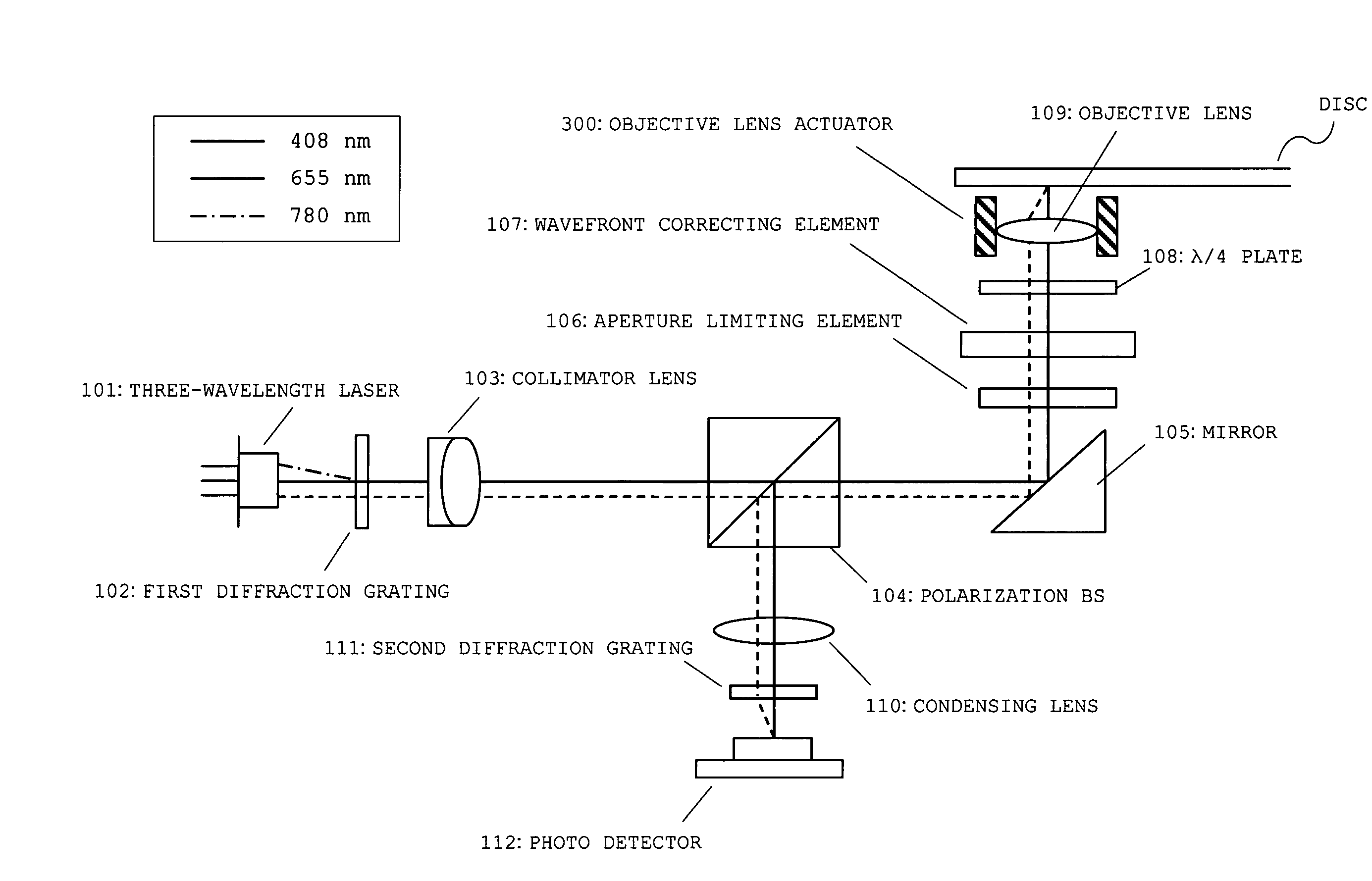
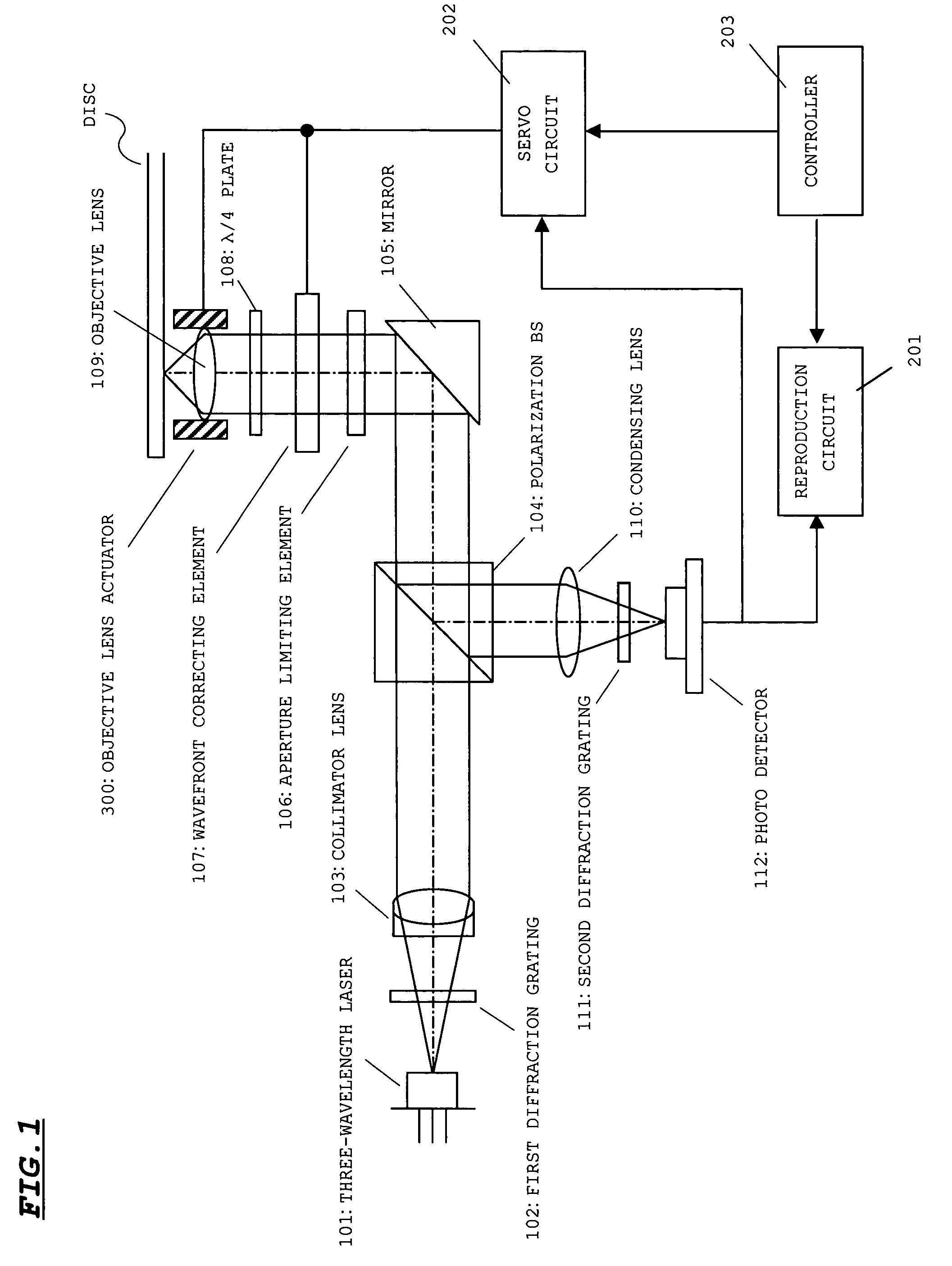
[0037]FIG. 1 shows a structure of an optical pickup device according to an embodiment of the present invention. The optical pickup device is used as a compatible device for CD / DVD / next-generation-DVD. In FIG. 1, a reproduction circuit 201, a servo circuit 202, and a controller 203 are components on the side of an optical disc apparatus.

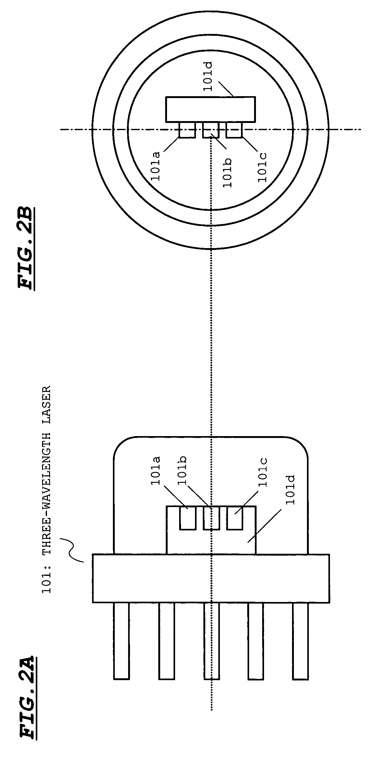
[0038]As shown in FIG. 1, the optical pickup device includes a three-wavelength laser 101, a first diffraction grating 102, a collimator lens 103, a polarization BS (beam splitter) 104, a mirror 105, an aperture limiting element 106, a wavefront correcting element 107, λ / 4 plate 108, an objective lens 109, a condensing lens 110, a second diffraction grating 111, a photo detector 112, and an objective len...


PUM

PropertyMeasurementUnit
wavelengthaaaaaaaaaa

Abstract

An optical pickup device that emits laser light beams having different wavelengths to a recording medium is disclosed. A semiconductor laser includes three laser elements having emitting wavelengths of λ1, λ2, and λ3 (λ1<λ2<λ3), respectively. A plurality of diffraction gratings substantially align optical axes of the laser light beams emitted from the laser elements with one another by diffracting action. The diffraction gratings are separately provided for corresponding laser light beams having wavelengths of λ2 and λ3. Diffracting action for aligning ±n-order diffraction light (n is an integer equal to or greater than 1) of each of the laser light beams having the wavelengths of λ2 and λ3 with an optical axis of a laser light beam having a wavelength of λ1 is provided for the laser light beams having the wavelengths of λ2 and λ3.

Description

BACKGROUND OF THE INVENTION[0001]1. Field of the Invention[0002]The present invention relates to an optical pickup device, and more particularly to an optical pickup device suitable for a compatible optical pickup device capable of emitting several kinds of laser light beams having different wavelengths to a recording medium.[0003]2. Description of the Related Art[0004]Currently, various optical discs such as a compact disc (CD) and a digital versatile disc (DVD) have been commercialized and widely used. Recently, next-generation DVD standardization for recording and reproducing information using a blue-violet laser light beam has been proceeded. In the next-generation DVD, information is recorded and reproduced using the blue-violet laser light beam having a wavelength of about 405 nm. When the wavelength of the laser light beam shortens, a higher density can be obtained.[0005]Therefore, when the variety of optical discs increases, development of a so-called compatible optical pick...

Claims


Application Information

Patent Timeline
Patent Type & Authority Patents(United States)
IPC IPC(8): G11B7/135G11B7/00G11B7/125G11B7/1353
CPCG11B7/1353G11B2007/0006
Inventor NAGATOMI, KENJIKAJIYAMA, SEIJI
Owner SANYO ELECTRIC CO LTD
Why Eureka
Try Eureka