Optical pickup device

a pickup device and optical technology, applied in the field of optical pickup devices, can solve the problems of deterioration of optical characteristics, increased cost of the optical pickup device as a whole, and difficult formation of laser elements, so as to achieve smooth and accurate performance, suppress the effect of cost increase and accurate performan

Inactive Publication Date: 2008-09-02
SANYO ELECTRIC CO LTD
View PDF6 Cites 0 Cited by
  • Summary
  • Abstract
  • Description
  • Claims
  • Application Information

AI Technical Summary

Benefits of technology

[0015]An object of the present invention is to provide an optical pickup device whose optical axis adjustment can be smoothly and accurately performed while an increase in cost is suppressed and whose optical axis correction can be accurately performed by employing a diffraction grating as an optical axis correction element even when a variation in arrangement or wavelengths between laser elements occurs.
[0045]According to the present invention, an inexpensive diffraction grating is used for an optical element for optical axis correction. Thus, the increase in cost of the optical pickup device can be suppressed. Also, an individual diffraction grating is prepared corresponding to a laser subject to optical axis correction. Thus, even when a variation from designed values occurs in arrangement or emission wavelengths of the laser elements, by adjusting the diffraction grating location in an optical axis direction, it is possible to conform the optical axis of the laser beam to the optical axis of the reference laser beam. At this time, the diffraction grating is arranged based on the above expressions (A) to (F) and its location is appropriately adjusted in the optical axis direction. Accordingly, the diffraction grating arrangement and location adjustment can be easily and smoothly performed.
[0046]According to the present invention, the laser beam optical axis adjustment can be easily and smoothly performed while the increase in cost of the optical pickup device is suppressed.

Problems solved by technology

Consequently, in the case of recording and reproduction using the other laser beams, there arises a problem in that aberration of laser beams is produced on a recording medium or a photo detector to cause deterioration of optical characteristics.
Since the birefringence element is expensive, a problem occurs in that a cost of the optical pickup device as a whole increases.
However, it is hard to form laser elements in which polarization planes of laser beams are made different from one another.
However, in manufacturing, it is nearly impossible to dispose the laser elements with the state in which they are approximated to each other to that degree.
Thus, it is very hard to align the optical axis of the laser beam for CD (780 nm in wavelength) and the optical axis of the laser beam for DVD (655 nm in wavelength) with that of the laser beam for next-generation DVD by using the birefringence element.
In this case, when a variation from designed values occurs in arrangement or emission wavelengths of the laser elements for the different wavelengths, the reflected laser beams having the different wavelengths cannot be adequately guided onto the photo detector.
However, it is impractical to redesign, every time a variation from designed values occurs, the diffraction grating according to the variation.
Therefore, in such case, practically there is no option but to use an existing diffraction grating without any modification assuming that no variation occurs.
However, in this case, optical axis correction cannot be adequately performed.

Method used


Image

  • Optical pickup device
  • Optical pickup device
  • Optical pickup device

Examples


Embodiment Construction

[0059]Hereinafter, an embodiment of the present invention will be described with reference to the accompanying drawings.

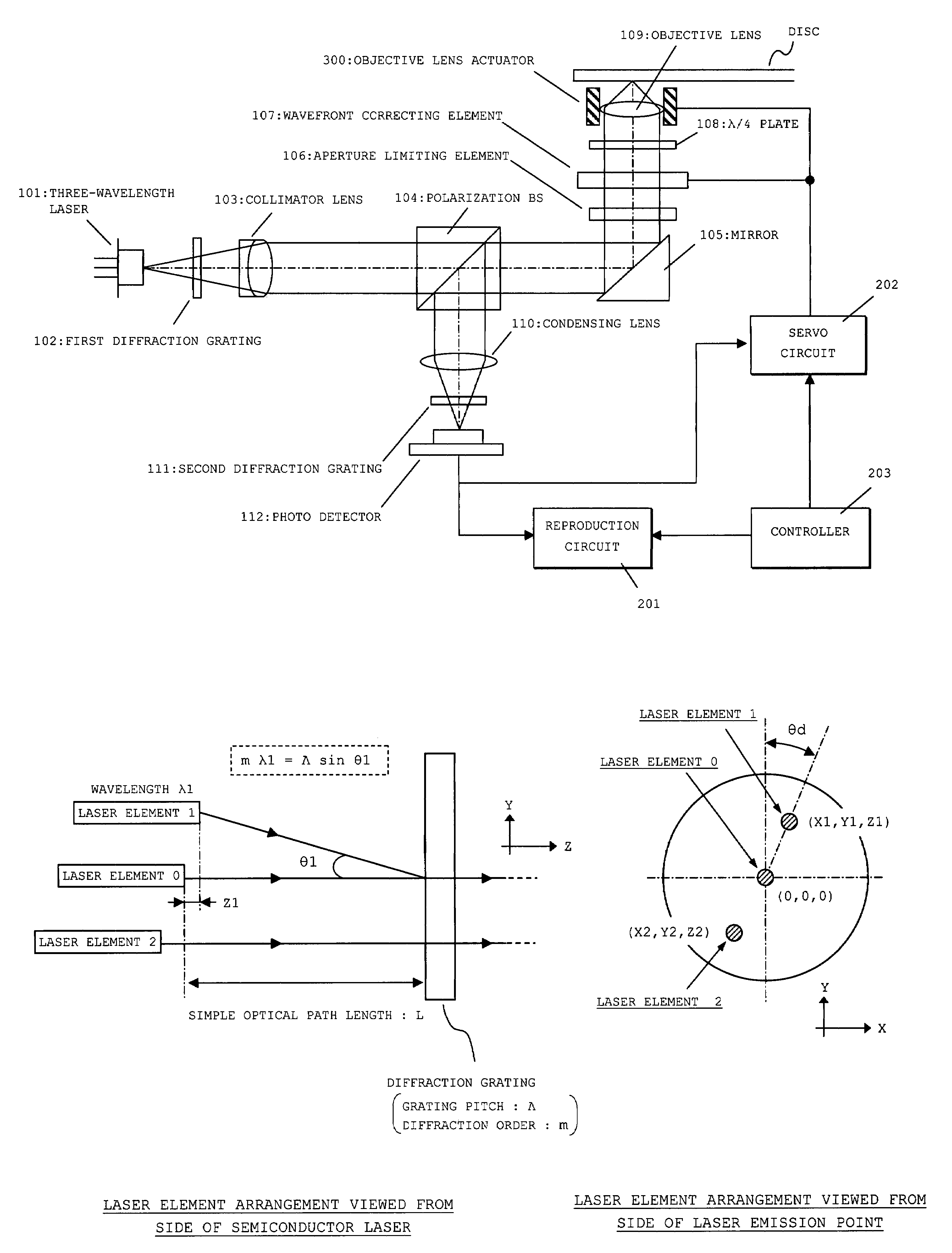
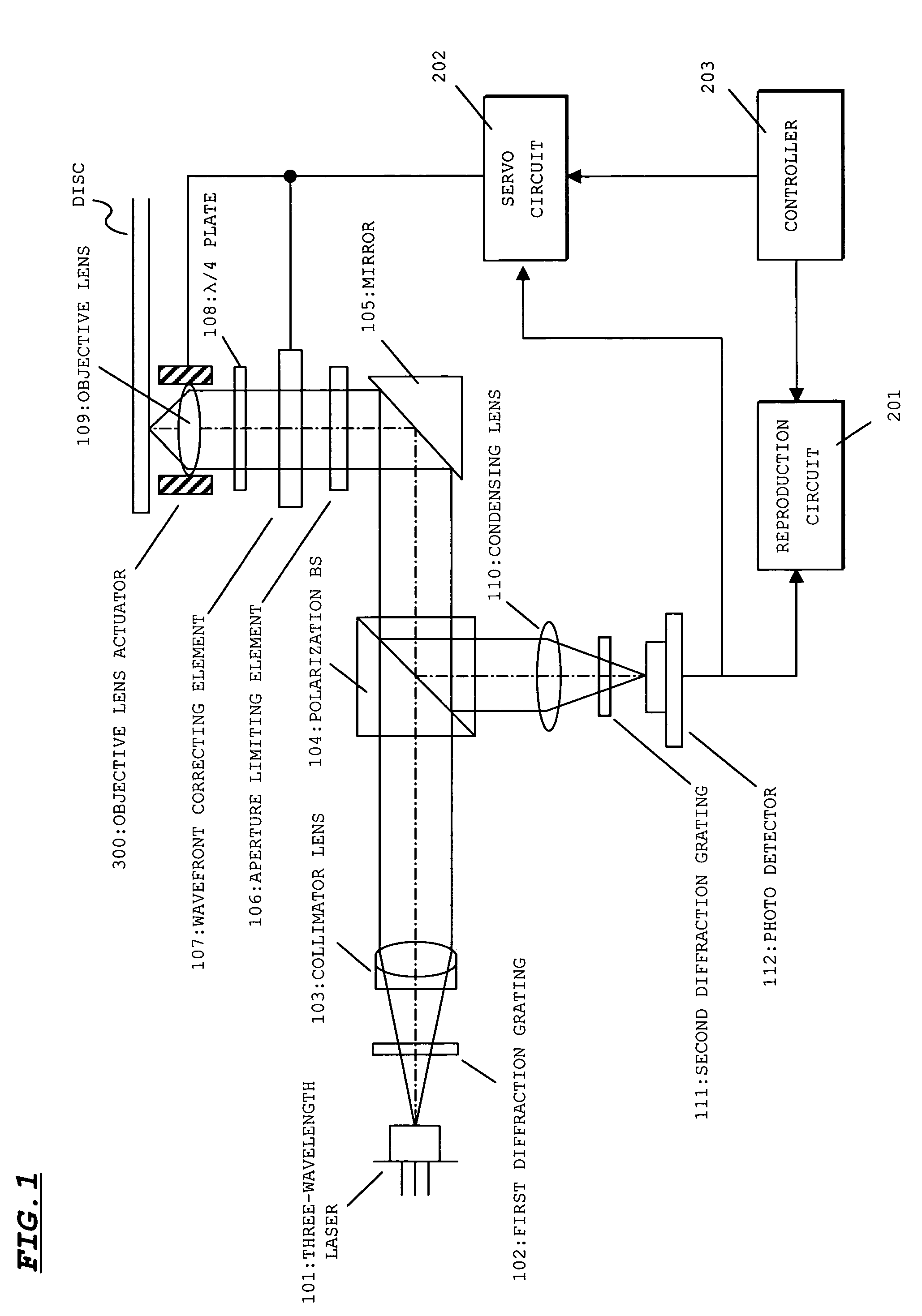
[0060]FIG. 1 shows a structure of an optical pickup device according to an embodiment of the present invention. The optical pickup device is used as a compatible device for CD / DVD / next-generation-DVD. In FIG. 1, a reproduction circuit 201, a servo circuit 202, and a controller 203 are components on the side of an optical disc apparatus.

[0061]As shown in FIG. 1, the optical pickup device includes a three-wavelength laser 101, a first diffraction grating 102, a collimator lens 103, a polarization BS (beam splitter) 104, a mirror 105, an aperture limiting element 106, a wavefront correcting element 107, a λ / 4 plate 108, an objective lens 109, a condensing lens 110, a second diffraction grating 111, a photo detector 112, and an objective lens actuator 300.

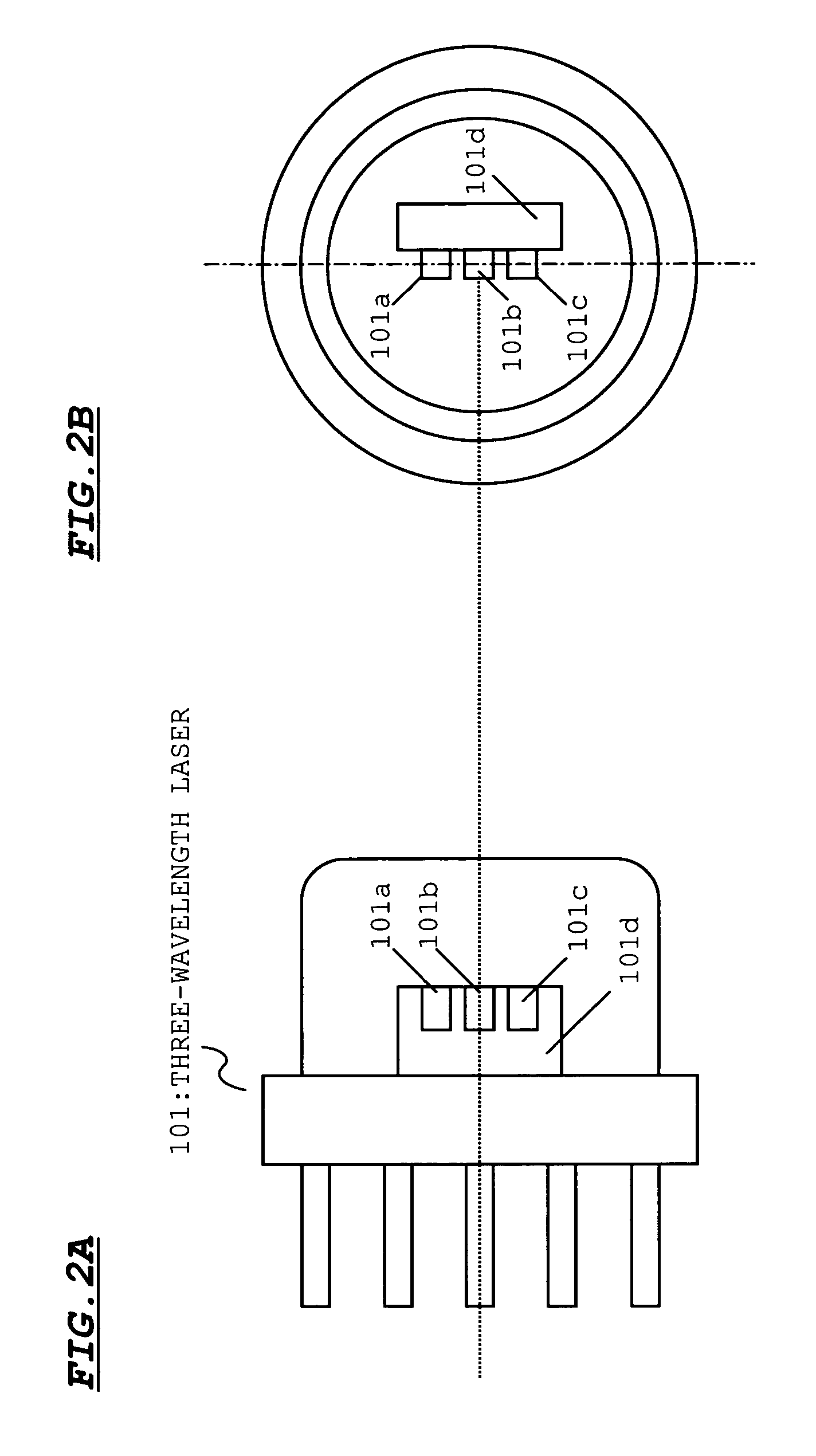
[0062]The three-wavelength laser 101 has three laser elements that emit a laser beam for CD (780 nm in wavelength),...


PUM

PropertyMeasurementUnit
wavelengthaaaaaaaaaa

Abstract

Provided is an optical pickup device whose optical axis adjustment can be performed while an increase in cost is suppressed and whose optical axis correction can be accurately performed even when a variation in arrangement between laser elements occurs. The optical pickup device includes a semiconductor 101 that houses at least three laser elements having at least three different emission wavelengths in a single package, and first and second diffraction gratings 102 and 111 for substantially matching optical axes of lasers emitted from the laser elements with the optical axis of the reference laser beam by a diffraction effect. The first diffraction grating 102 matches an optical axis of a laser beam for CD (780 nm in wavelength) with the reference optical axis by a diffraction effect. The second diffraction grating 111 matches an optical axis of a laser beam for DVD (655 nm in wavelength) with the reference optical axis by a diffraction effect. Even when a variation occurs in a light emitting point gap between the laser elements, by performing fine adjustment of the corresponding diffraction grating in the reference optical axis direction, the optical axis of the laser beam can be adjusted.

Description

BACKGROUND OF THE INVENTION[0001]1. Field of the Invention[0002]The present invention relates to an optical pickup device, and more particularly to an optical pickup device suitable for a compatible optical pickup device for emitting several kinds of laser beams having different wavelengths to a recording medium.[0003]2. Description of the Related Art[0004]Currently, various optical discs such as a compact disc (CD) and a digital versatile disc (DVD) have been commercialized and widely used. Further, recently, next-generation DVD standardization for recording and reproducing information using a blue-violet laser beam has been proceeding. In the next-generation DVD, information is recorded and reproduced using the blue-violet laser beam having a wavelength of about 405 nm. When the wavelength of the laser beam shortens, a higher density can be obtained.[0005]Therefore, when the variety of optical discs increases, development of a so-called compatible optical pickup device capable of ...

Claims


Application Information

Patent Timeline
Patent Type & Authority Patents(United States)
IPC IPC(8): G11B7/20G11B7/135G11B7/125
CPCG11B7/1275G11B7/1353G11B2007/0006
Inventor NAGATOMI, KENJIKAJIYAMA, SEIJI
Owner SANYO ELECTRIC CO LTD
Why Eureka
Try Eureka