Lighting device

a technology of light source and look-alike, which is applied in the direction of point-like light source, lighting and heating apparatus, light source, etc., can solve the problems of not being able to make glass, and compromising the look and feel of incandescent look-alik

Active Publication Date: 2020-01-28
SIGNIFY HLDG BV
View PDF5 Cites 0 Cited by
  • Summary
  • Abstract
  • Description
  • Claims
  • Application Information

AI Technical Summary

Benefits of technology

[0007]It is an object of the present invention to overcome or at least alleviate the aforementioned problems, and to provide an improved lighting device.
[0009]The glass bulb and tubular flare of the present lighting device can easily be manufactured on a standard incandescent bulb production line. The tubular flare, which may be a standard size extruded (therefore very smooth and accurate) glass tube, also allows for a good interface—both mechanically and thermally—with the heat spreader. And the glass bulb does not have to be glued to a separate part which in turn connects it to the end cap. Instead, the cylindrical heat spreader sticking out from the bulb / flare is simply pressed into the end cap. Overall, the present lighting device is such that it can be made on existing GLS lines, which makes it not only cheap and lightweight, but it also very much may look like GLS lamps.
[0012]The end cap may about the joint glass bulb and tubular flare. Hence, the transition between end cap and glass bulb may be smooth and very much like in a GLS lamp with no intermediate part.
[0013]The end cap may be attached to the second section of the cylindrical heat spreader such that the cylindrical heat spreader has a direct thermal connection to the end cap. This may increase the thermal performance of the lighting device.
[0014]The lighting device may further comprise a driver insulator provided between the cylindrical heat spreader and the driver. The driver insulator may be an inner dielectric coating or separate electrical insulator, for example. The driver insulator can be cheaply produced by, e.g. thermoforming.
[0018]As mentioned above, the glass bulb and tubular flare can easily be manufactured on a standard incandescent bulb line. A gripper may be used, replacing the pump tube, so that the flare can be sealed to the bulb on the existing lines.

Problems solved by technology

However, this compromises the look and feel of an incandescent look-alike.
However, a problem with the LED candle lamp in CN103322460 is that it is not makeable in glass, at least not with high volume production methods, because of the gradually thicker cross section of the lamp shade towards the lamp support (see FIG. 3 in CN103322460).

Method used


Image

  • Lighting device
  • Lighting device
  • Lighting device

Examples


Embodiment Construction

[0027]The present invention will now be described more fully hereinafter with reference to the accompanying drawings, in which currently preferred embodiments of the invention are shown. This invention may, however, be embodied in many different forms and should not be construed as limited to the embodiments set forth herein; rather, these embodiments are provided for thoroughness and completeness, and fully convey the scope of the invention to the skilled person.

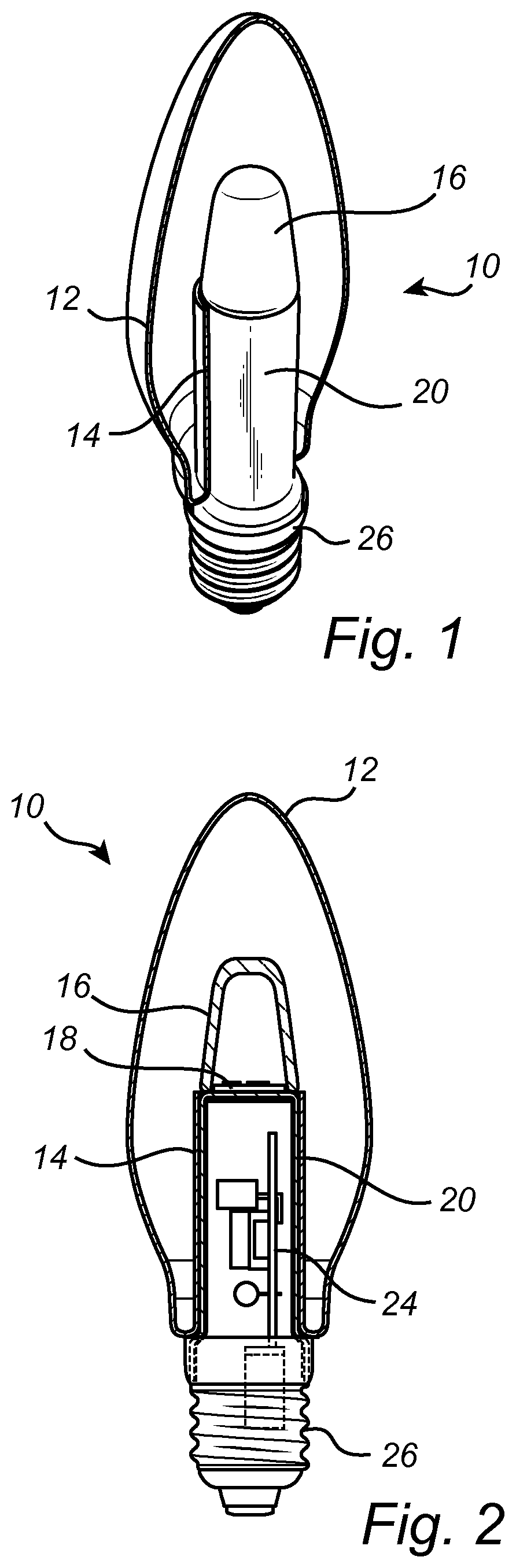
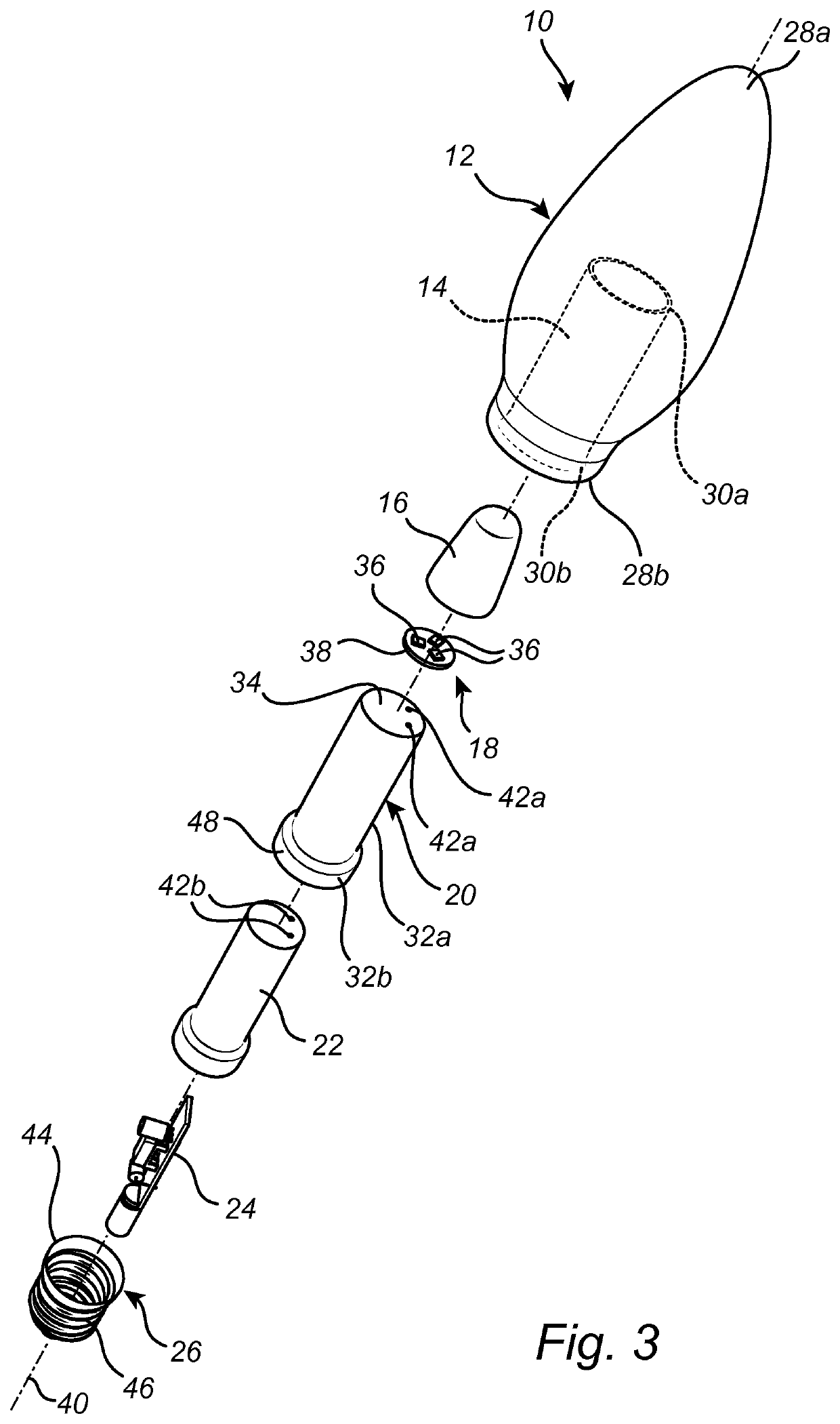
[0028]FIGS. 1-3 illustrate a lighting device 10 according to an embodiment of the present invention. The lighting device 10 in FIGS. 1-3 is an LED (light emitting diode) candle lamp. The lighting device 10 may be a retrofit lamp.

[0029]From top to bottom as seen in FIG. 3, the lighting device 10 comprises a glass bulb 12 with a tubular flare 14, optical means 16, a solid-state lighting (SSL) unit 18, a heat spreader 20, a driver insulator 22, a driver 24, and an end cap 26.

[0030]The glass bulb 12 is candle-shaped (“B-shape”)...


PUM


Abstract

Lighting device (10), comprising: a glass bulb (12); a tubular flare (14) having an open distal and (30a), provided inside the glass bulb (12) and joined with the glass bulb (12); a cylindrical heat spreader (20) having a first section (32a) arranged inside the tubular flare (14) and a second section (32b) extending outside the tubular flare (14) and the glass bulb (12); a solid-state lighting unit (18) mounted on top of the first section (32a); an optical means (16) provided over the solid state lighting unit (18); said open distal end (30a) being arranged for positioning the optical means (16) outside the tubular flare (14); a driver (24) provided at least partly inside the cylindrical heat spreader (20) and electrically connected to the solid-state lighting unit (18); and an end cap (26) attached to the second section (32b) of the cylindrical heat spreader (20).

Description

[0001]This application is the U.S. National Phase application under 35 U.S.C. § 371 of International Application No. PCT / EP2017 / 066476, filed on Jul. 3, 2017 which claims the benefit of European Patent Application No. 16179512.5, filed on Jul. 14, 2016. These applications are hereby incorporated by reference herein.FIELD OF THE INVENTION[0002]The present invention relates to a lighting device, such as an LED (light emitting diode) candle lamp. The present invention also relates to a method of manufacturing such a lighting device.BACKGROUND OF THE INVENTION[0003]There are currently many LED candle lamps on the market that try to mimic the look and feel of the incandescent candle lamps. All current LED candle lamps, with the exception of LED filament bulbs, have some sort of interface part between the bulb and the end cap. However, this compromises the look and feel of an incandescent look-alike.[0004]CN103322460 discloses an LED candle lamp comprising a lamp holder, a drive power sou...

Claims


Application Information

Patent Timeline
Patent Type & Authority Patents(United States)
IPC IPC(8): F21K9/232F21K9/237F21V29/70F21K9/235F21V3/02F21K9/90F21V23/00F21V3/06F21Y101/00F21Y115/10
CPCF21V3/02F21K9/235F21K9/237F21V29/70F21K9/232F21V23/009F21Y2101/00F21V3/061F21Y2115/10F21K9/90
Inventor GIELEN, VINCENT STEFAN DAVID
Owner SIGNIFY HLDG BV
Why Eureka
Try Eureka