Operation support device and assembly method thereof

a technology of operation support and assembly method, which is applied in the direction of surgical staples, surgical forceps, applications, etc., can solve the problems of difficult sterilization treatment on the uni

Active Publication Date: 2014-06-19
OLYMPUS CORP
View PDF3 Cites 127 Cited by
  • Summary
  • Abstract
  • Description
  • Claims
  • Application Information

AI Technical Summary

Problems solved by technology

However, for example, it is difficult to perform the sterilization treatment o...

Method used


Image

  • Operation support device and assembly method thereof
  • Operation support device and assembly method thereof
  • Operation support device and assembly method thereof

Examples


first embodiment

[0068]An operation support device according to a first embodiment of the present invention will be described.

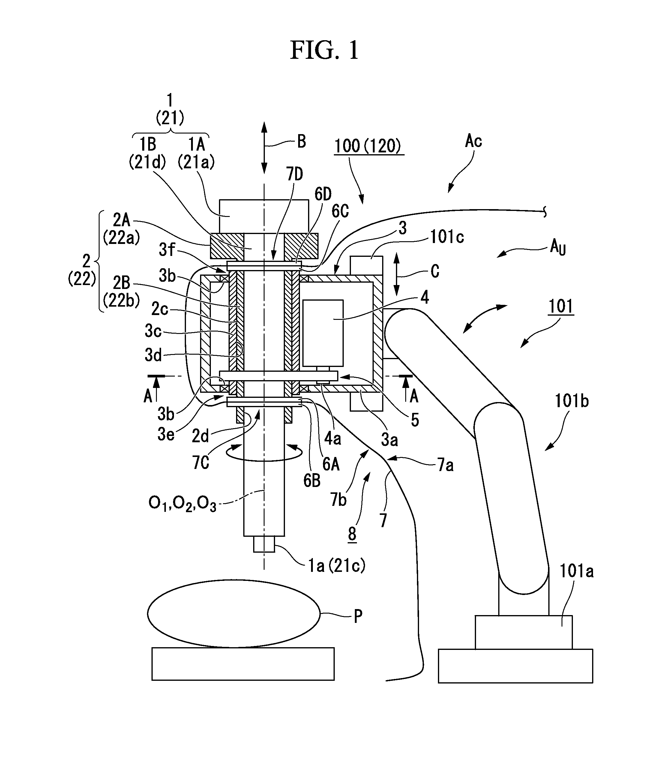
[0069]FIG. 1 is a schematic partial cross-sectional view showing a configuration of the operation support device according to the first embodiment of the present invention. FIG. 2 is a cross-sectional view taken along line A-A of FIG. 1. FIG. 3 is a schematic perspective view showing a configuration of a shielding member of the operation support device according to the first embodiment of the present invention.

[0070]As shown in FIG. 1, for example, in a surgical operation, an operation support device 100 according to the present embodiment is an apparatus for manipulating a surgical instrument or moving the surgical instrument in a state in which the surgical instrument is disposed at an appropriate position such as a body cavity of a patient P, or the like.

[0071]The operation support device 100 includes a surgical instrument unit support section 101, a surgical instrument dr...

first modified example

[0176]Next, an operation support device according to a modified example (a first modified example) of the present embodiment will be described.

[0177]FIG. 7 is a schematic partial cross-sectional view showing a configuration of main parts of the operation support device according to the modified example (the first modified example) of the first embodiment of the present invention.

[0178]As shown in FIG. 7, an operation support device 110 according to the present modified example includes a drape assembly 18 (a shielding member), a surgical instrument driving unit 13 (a driving force supply unit), an intermediate member 12, and a treatment tool unit 11 (a surgical instrument unit), instead of the drape assembly 8, the surgical instrument driving unit 3, the intermediate member 2, and the treatment tool unit 1 included in the operation support device 100 according to the first embodiment, respectively.

[0179]The surgical instrument driving unit 13 includes a shaft rotating member 13c, in...

second embodiment

[0220]Next, the operation support device according to a second embodiment of the present invention will be described. The present embodiment is an embodiment of a case in which a force for driving a surgical instrument distal end of a treatment tool unit is transmitted from a surgical instrument driving unit via an intermediate member.

[0221]FIG. 8 is a schematic perspective view showing an appearance of main parts of an operation support device according to the second embodiment of the present invention. FIG. 9 is a schematic cross-sectional view of the main parts of the operation support device according to the second embodiment of the present invention upon connection in an axial direction. FIG. 10 is a schematic cross-sectional view of the main parts of the operation support device according to the second embodiment of the present invention upon disconnection in the axial direction. FIG. 11 is a schematic cross-sectional view of a surgical instrument unit drive unit and an interm...


PUM

PropertyMeasurementUnit
Forceaaaaaaaaaa

Abstract

An operation support device having a surgical instrument unit and a surgical instrument unit support section, includes: an intermediate member connected to the surgical instrument support section and configured to hold the surgical instrument unit; a shielding member having a hole portion engaged with the intermediate member; and a driving force supply unit installed at the surgical instrument support section. A first space and a second space are formed by an assembly constituted by the shielding member and the intermediate member engaged with the hole portion as a boundary. The intermediate member is connected to the surgical instrument support section at a side of the first space, and holds the surgical instrument unit at a side of the second space. The driving force supply unit and the surgical instrument support section are disposed in the first space.

Description

[0001]This application is a continuation application based on a PCT Patent Application No. PCT / JP2012 / 070408, filed Aug. 3, 2012, whose priority is claimed on both U.S. Provisional Application No. 61 / 515,203, filed on Aug. 4, 2011, and Japanese Patent Application No. 2012-036226, filed on Feb. 22, 2012. The contents of all of the PCT Application, the US Provisional Application, and the Japanese Application are incorporated herein by reference.BACKGROUND OF THE INVENTION[0002]1. Field of the Invention[0003]The present invention relates to an operation support device and an assembly method thereof.[0004]2. Description of Related Art[0005]In the related art, in order to support a surgical operation, an operation support device in which a surgical instrument unit is supported by a surgical instrument unit support section is well known.[0006]In such an operation support device, in order to prevent contamination to a patient or a treated subject (hereinafter, simply referred to as a subje...

Claims


Application Information

Patent Timeline
IPC IPC(8): A61B19/00A61B19/08A61B46/23
CPCA61B19/081A61B19/26A61B2017/00477A61B46/23A61B34/71A61B90/50A61B34/30A61B46/10A61B34/37A61B34/77Y10T74/18056Y10T29/49826Y10S901/08Y10S901/09Y10S901/30A61B17/068A61B17/29A61B17/32002A61B18/1402A61B2017/00119A61B2017/00482B25J13/02G06F3/01
Inventor KISHI, KOSUKE
Owner OLYMPUS CORP
Why Eureka
Try Eureka