Screw cap with a cutting sleeve

a screw cap and cutting sleeve technology, applied in the field of screw caps, can solve the problems of difficult to achieve metered dispensing, high and controlled, and achieve the effect of reducing the chance of liquid spilling ou

Inactive Publication Date: 2014-07-17
ROBERT BOSCH GMBH
View PDF3 Cites 16 Cited by
  • Summary
  • Abstract
  • Description
  • Claims
  • Application Information

AI Technical Summary

Benefits of technology

[0008]Such a screw cap is preferably embodied such that the cutting sleeve is designed to have double walls below the lateral metering opening, comprising an unthreaded inner lateral wall having a terminal cutting edge and an outer lateral wall having internal thread which mesh with the thread on the lower part, and such that the outer lateral wall is shorter in an axial direction than the height of the cylindrical tubular section of the lower part. In this way, the cutting sleeve can now be grasped from the outside and actuated by hand independently of the screwing movement of a screw cap. Whereas the container can thus be opened while the screw cap is still closed, the danger does not exist that liquid is already squeezed out of the container during opening.

Problems solved by technology

A controlled, metered dispensing is, however, difficult to achieve.
Because the screw cap is completely screwed off with the screw closures comprising a cutting sleeve known to date, the complete passageway in the cutting sleeve is open and the chance is extremely great that the liquid spills out merely by lifting the receptacle.

Method used


Image

  • Screw cap with a cutting sleeve
  • Screw cap with a cutting sleeve
  • Screw cap with a cutting sleeve

Examples


Embodiment Construction

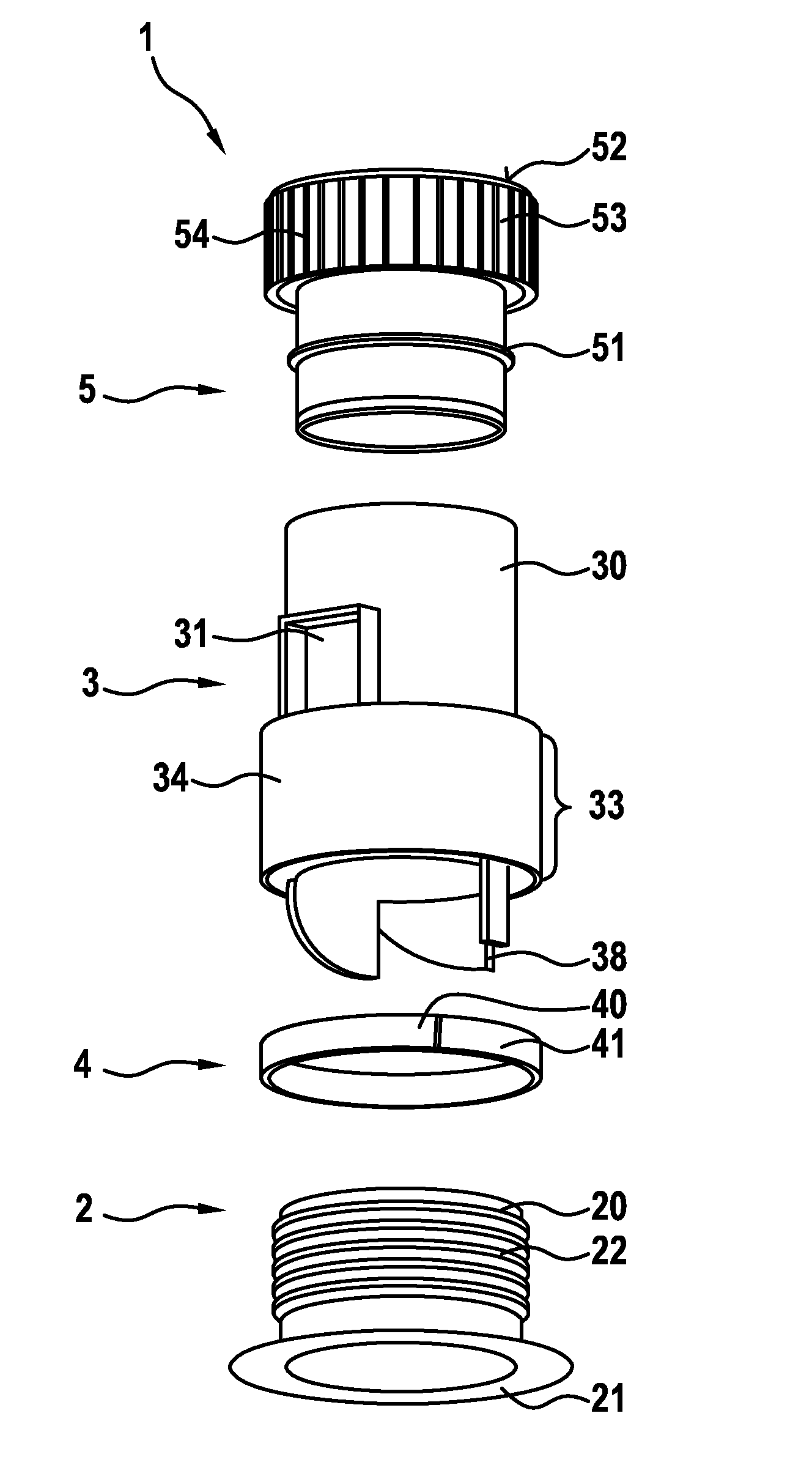
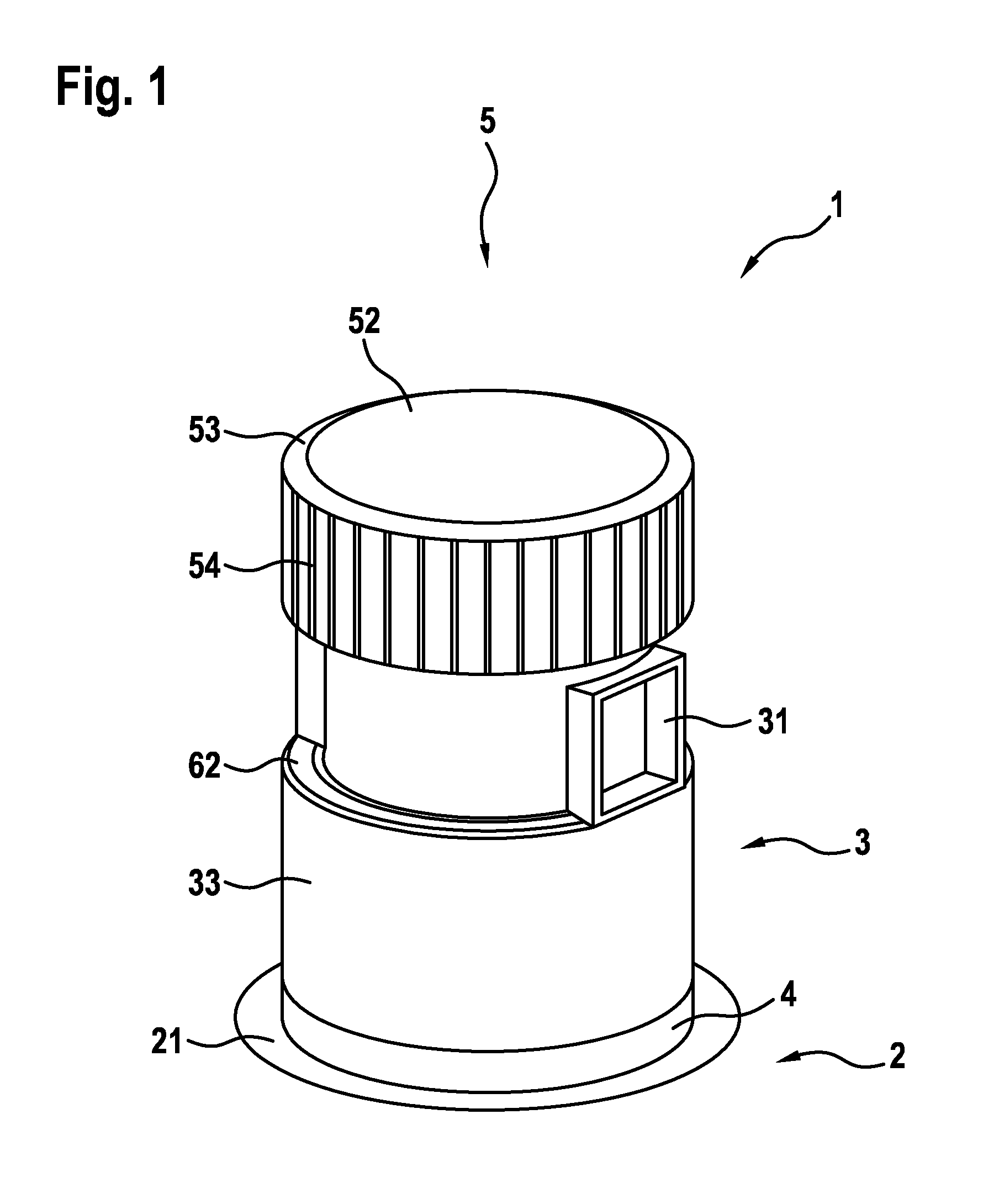
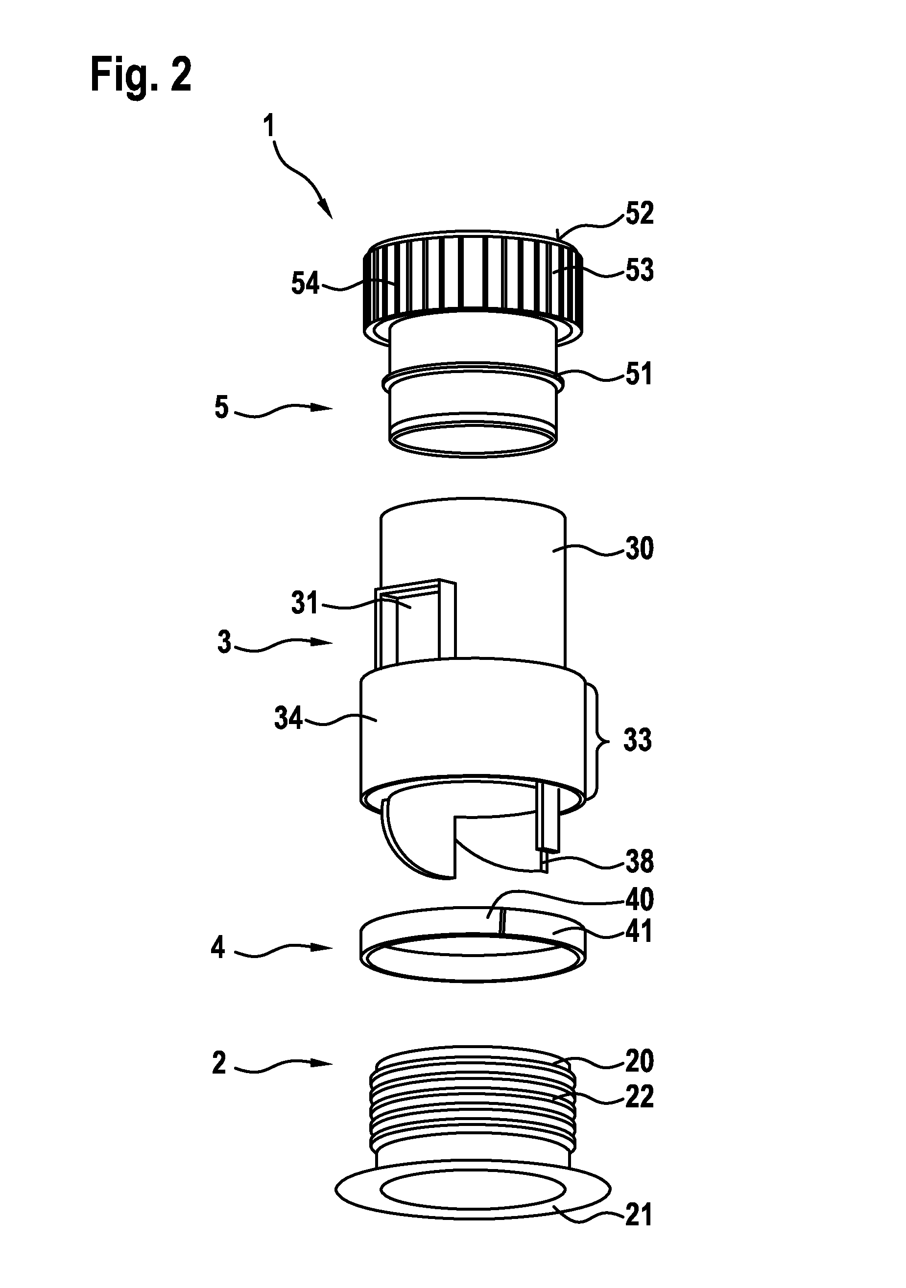
[0015]The self-opening screw cap is denoted in its entirety with the reference numeral 1. The same screw cap could however be just as well referred to as a metering closure because the invention relates to a combination of a self-opening screw cap and a metering closure. The inventive screw cap consists of four components, namely a lower part 2, a cutting sleeve 3, a spacing means 4 and a valve piston 5 which is designed as a rotary handle in the uppermost region, wherein only this part is visible in the assembled state. The screw cap of interest here is, as previously mentioned, mounted on a closed container made of film. To this end, the lower part 2 comprises an outwardly protruding, circumferential flange 21. The cutting sleeve 3 has a lateral metering opening 31, which in this case is implemented relatively large as a square window. Prior to initial use, the spacing means 4 is still present, which can be embodied either as a spacing ring or as a tamperproof strip 40. On the one...


PUM

PropertyMeasurementUnit
heightaaaaaaaaaa
sizeaaaaaaaaaa
axial displacementaaaaaaaaaa

Abstract

For the first time, a screw cap (1) is realized with which a tubular bag to which the screw cap (1) is attached can be opened by a self-cutting process and metered dispensing from a metering opening (31) is simultaneously realized. The screw cap (1) consists of a lower part (2), on which a spacing means (4), used in practical terms as transport protection, is placed, and onto which a cutting sleeve (3) with a lateral metering opening (31) is screwed. The container can be opened by means of the cutting sleeve (3) and thereafter its contents can be dispensed in a metered manner by means of a valve piston (5) that is guided in the cutting sleeve (3) by a screwing movement. In the closed state, the valve piston (5) reaches into the cylinder (30) of the cutting sleeve (3) underneath the metering opening (31) and seals the cylinder (30), which is open at both ends, off against the container that is welded to the flange (21) of the lower part (2).

Description

BACKGROUND OF THE INVENTION[0001]The present invention relates to a screw cap, consisting of a lower part, which comprises a cylindrical threaded tubular section and a terminal flange for attaching to a closed container made from film material, and a cutting sleeve connected to the thread of the lower part by means of a threaded connection.[0002]Screw caps of the kind mentioned above have already been known since the late 1980s. For example, the European patent application EP 0328652 discloses such a cap. Further modifications thereto are disclosed, for example, by the U.S. Pat. No. 5,147,070, the WIPO patent application 99 / 62776, the WIPO patent application 2004 / 083055 and many others. Closures of this kind use entraining elements to drive the cutting sleeve, said elements being mounted to the bottom of the top surface of the screw cap. If said screw cap is unscrewed, the cutting sleeve moves simultaneously in a rotary motion which is in the same direction but has opposite axial di...

Claims


Application Information

Patent Timeline
Patent Type & Authority Applications(United States)
IPC IPC(8): B67D1/00
CPCB65D47/38B65D51/243B65D5/748B65D75/5877B65D47/247B65D2401/25
Inventor BARRON, DAN
Owner ROBERT BOSCH GMBH
Why Eureka
Try Eureka