Lighting device and method for operating the lighting device

a lighting device and a technology for lighting devices, applied in the direction of instrumentation, process and machine control, pulse technique, etc., can solve the problems of not being able to design a lighting device by, and the construction of these lighting devices is not very narrow in the vertical direction, so as to facilitate the finding of light-emitting elements

Active Publication Date: 2014-07-17
HELLA KG HUECK & CO
View PDF15 Cites 15 Cited by
  • Summary
  • Abstract
  • Description
  • Claims
  • Application Information

AI Technical Summary

Benefits of technology

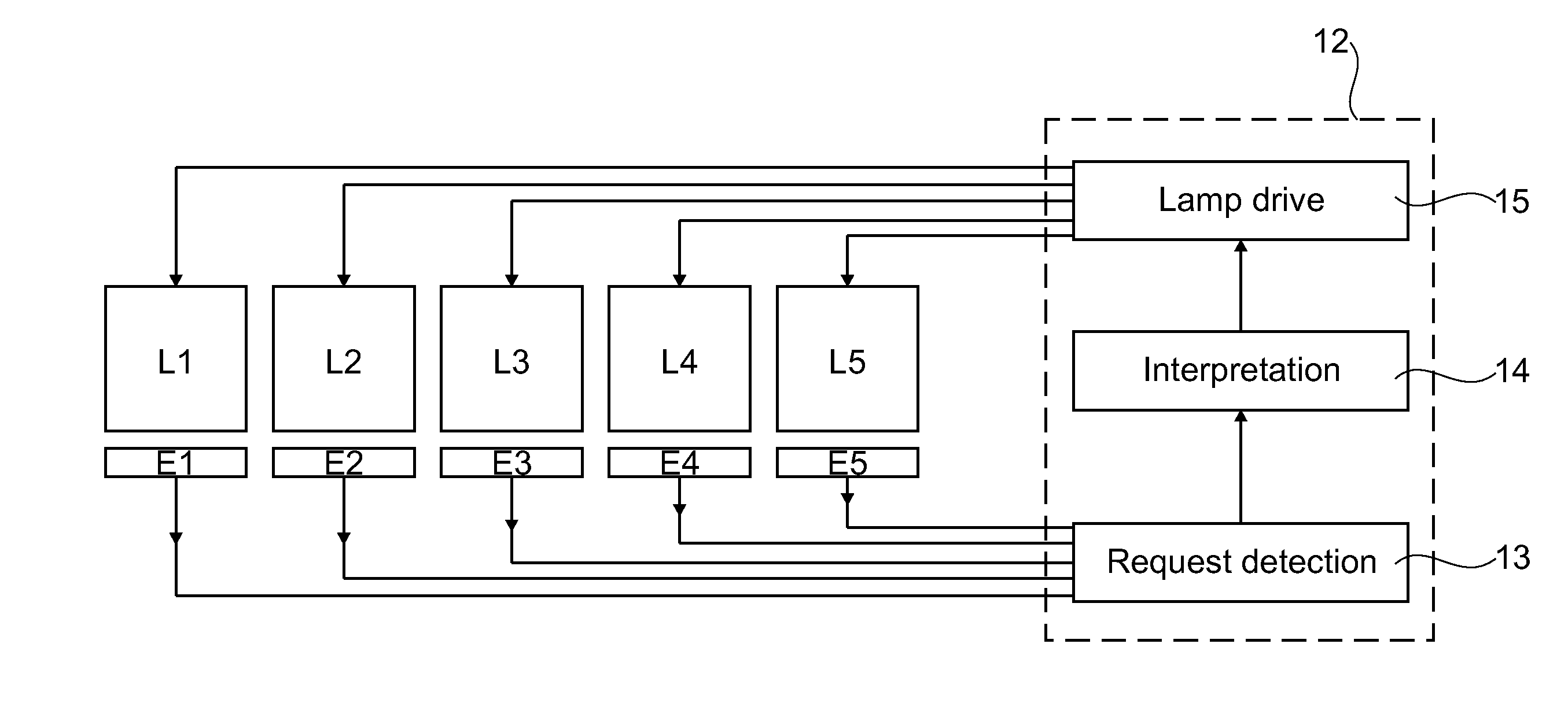
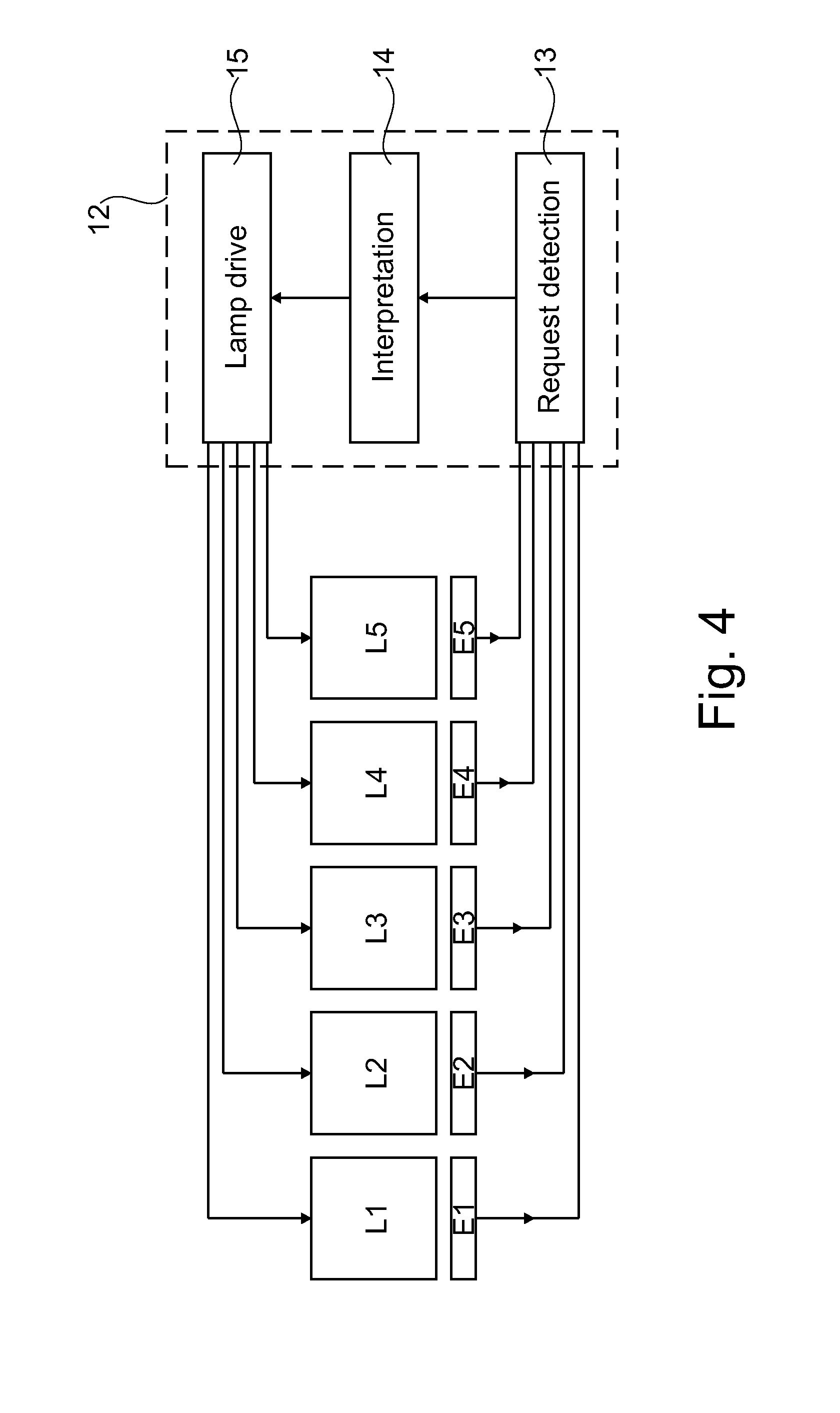
[0040]It is also appropriate if with an approach of the hand toward a control element or toward a first light-emitting element with an associated control element, the light-emitting element brightens up or lights up if the distance of the hand has already reached or dropped below a first threshold value for the distance but has not yet reached a second, smaller threshold value, the light-emitting element being lit maximally when the second threshold value is reached or undershot. By this means, easier finding of the light-emitting elements in the dark can be achieved.
[0041]It is advantageous if darkening or extinction of the light-emitting element takes place when the distance of the hand increases again after reaching or dropping below the first threshold value. By this means, it is achieved that the lighting of the light-emitting element is reduced again, that is to say darkened, when the hand is retracted again from a certain position of the hand which leads to the at least beginning lighting-up.

Problems solved by technology

However, the construction of these lighting devices is not very narrow in the vertical direction.
However, it is not possible to design a lighting device by this means, especially for the rear area or the front area of the vehicle passenger compartment.
If all light-emitting elements are switched off, this would thus result in switching-on.

Method used


Image

  • Lighting device and method for operating the lighting device
  • Lighting device and method for operating the lighting device
  • Lighting device and method for operating the lighting device

Examples


Embodiment Construction

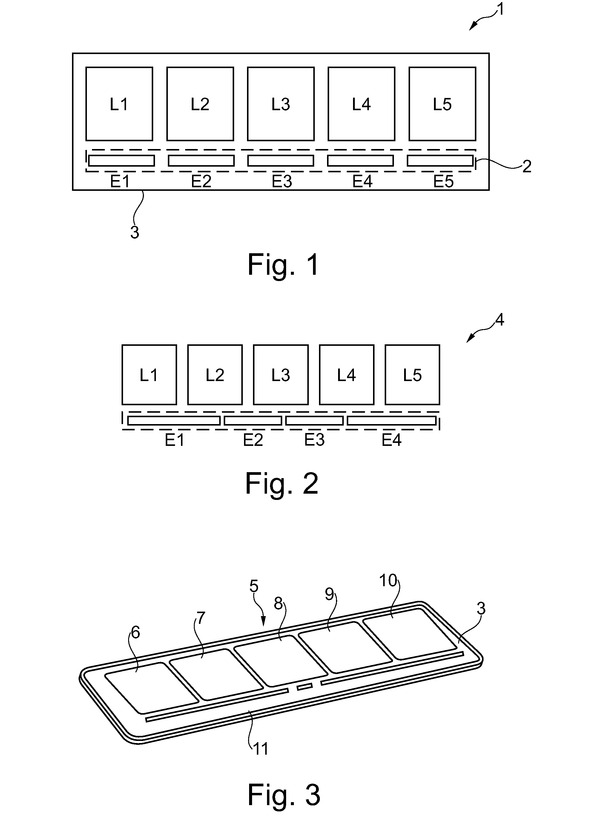
[0064]FIG. 1 shows a lighting device 1 having a first number N1 of light-emitting elements L1, L2, L3, L4, L5, wherein also a second number N2 of control elements E1, E2, E3, E4, E5 advantageously operating contactlessly is provided.

[0065]The control elements E1 to E5 are used for switching the light-emitting elements L1 to L5 on or off and / or controlling their brightness. In this context, a light-emitting element can be driven continuously by PWM modulation in its brightness or it can be switched on or off completely.

[0066]The light-emitting elements L1 to L5 are represented as two-dimensional, for example rectangular or square light-emitting elements which are arranged next to one another in one row. The control elements E1 to E5 are represented as narrow rectangular elements which are also arranged next to one another flush in one row with one another. The light-emitting elements L1 to L5 are in this case arranged in one row, the row of light-emitting elements being arranged in p...


PUM


Abstract

The invention relates to a lighting device having a first number of light-emitting elements and having a second number of control elements, operating contactlessly, for controlling the light-emitting elements such as especially for switching the light-emitting elements on or off and/or for controlling their brightness, the second number being less than or equal to the first number, the light-emitting elements being controlled contactlessly by a movement of at least one hand of a user over two or more control elements. The invention also relates to a relevant method.

Description

TECHNICAL FIELD[0001]The invention relates to a lighting device and a method for operating a lighting device.PRIOR ART[0002]In the prior art, lighting devices are known which are applied in the vehicle passenger compartment. In this context, light-emitting elements are used which are in each case switched on by means of mechanical switches and locally generate a light for an operator or passenger. However, the construction of these lighting devices is not very narrow in the vertical direction.[0003]Lighting devices have also become known which comprise a proximity sensor as is disclosed in DE 10 2005 005 411 A1. This printed document discloses an control element which is illuminated when approached with a hand. However, it is not possible to design a lighting device by this means, especially for the rear area or the front area of the vehicle passenger compartment.PRESENTATION OF THE INVENTION, OBJECT, SOLUTION, ADVANTAGES[0004]It is the object of the present invention, therefore, to...

Claims


Application Information

Patent Timeline
Patent Type & Authority Applications(United States)
IPC IPC(8): H05B37/02H05B44/00
CPCH05B37/0227H05B47/175H05B47/115Y02B20/40H03K17/962
Inventor HEINRICH, JURGEN
Owner HELLA KG HUECK & CO
Why Eureka
Try Eureka