Patient interface device with limited support area on the face
a technology of patient interface and support area, which is applied in the direction of breathing mask, breathing protection, other medical devices, etc., can solve the problems of gas leakage around the periphery of the mask, compression of the mask cushion,
- Summary
- Abstract
- Description
- Claims
- Application Information
AI Technical Summary
Benefits of technology
Problems solved by technology
Method used
Image
Examples
first embodiment
[0050]FIGS. 5-10 illustrate a patient interface device 100 according to the principles of the present invention. Patient interface device 100 is shown in FIG. 6 schematically connected to a ventilator or pressure support system 10 via a patient circuit 12, which communicates gas from the pressure support system to the patient interface device. For purposes of the present invention, pressure support system 10 is any conventional ventilation or pressure support system that includes a gas flow generating device capable of delivering a flow of gas to the user. Patient circuit 12 is any device, such as a flexible tubing, that carries the flow of gas from the pressure / flow generator in the pressure support system to the patient interface device. In this schematic illustration, the patient circuit includes a single hose that is coupled to the pressure support system, a Y-connector or Y-junction, and two separate hoses that diverge from the Y-connector and are connected to each side of the ...
second embodiment
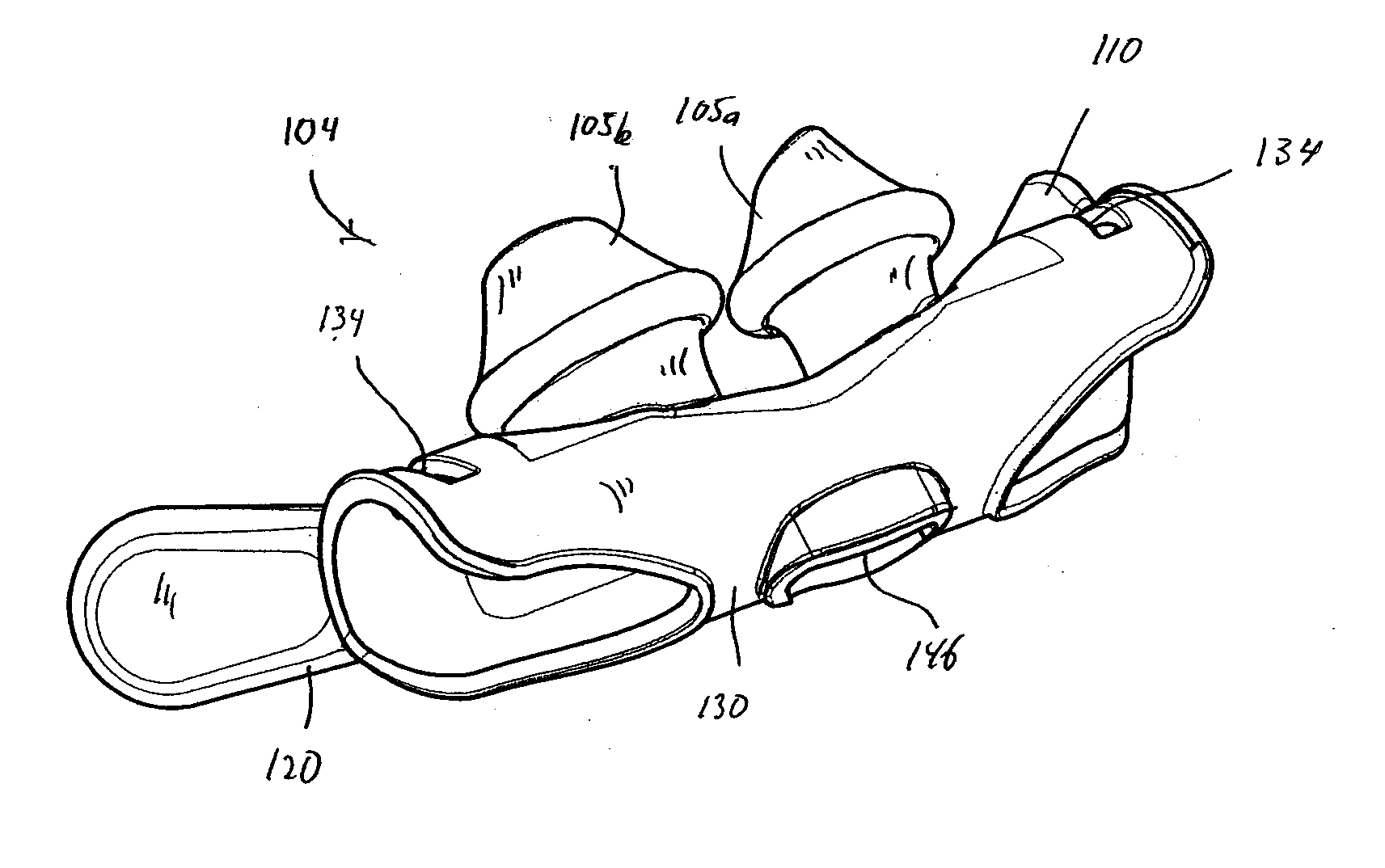
[0064]FIGS. 11-16 illustrate a patient interface device 200 according to the principles of the present invention. Patient interface device 200 includes a support member 202 and a sealing assembly 204 coupled to support member. Support member 202 includes an internal passage or lumen 206 that serves as a pathway for the flow of gas to and from the user. As in the previous embodiment, one or both ends of support member 202 are coupled to a pressure support system.
[0065]Sealing assembly 204 is a pair of nasal prongs 205a and 205b with openings 208a and 208b provided in each prong to communicate gas in lumen 206 to the airway of the user. As in the previous embodiment, each prong has a “mushroom” configuration with a stem portion 207a, 207b and a head portion 209, 209b. Of course, other embodiments for the nasal prongs, as well as the entire sealing assembly are contemplated by the present invention. For example, the sealing assemblies set forth in subsequent embodiments are contemplate...
third embodiment
[0071]FIGS. 17-21 illustrate a patient interface device 300 according to the principles of the present invention. This embodiment is generally similar to that of FIGS. 11-16 in that a sealing assembly 304 is mounted onto a support member 302, and first and second pads 312 and 322 are coupled to the support member via a support frame 340 that is also attached to the support member.
[0072]In this embodiment sealing, however, assembly 304 takes the form of a single cushion 305 attached or attachable to the support member, rather than a pair of nasal prongs or cannulae. Support member 302 is a rigid, semi-rigid, or flexible tube having a cylindrical shape with a passage 306 defined therein. Of course, other shapes and configurations for support member are contemplated by the present invention.
[0073]Cushion 305 is sized and configured to seal around the nares of the user and includes a single opening 308 to communicate the user's airway with passage 306 in support member 302. Thus, the ar...
PUM
 Abstract
Description
Claims
Application Information
 - R&D
- Intellectual Property
- Life Sciences
- Materials
- Tech Scout
- Unparalleled Data Quality
- Higher Quality Content
- 60% Fewer Hallucinations
Browse by: Latest US Patents, China's latest patents, Technical Efficacy Thesaurus, Application Domain, Technology Topic, Popular Technical Reports.
© 2025 PatSnap. All rights reserved.Legal|Privacy policy|Modern Slavery Act Transparency Statement|Sitemap|About US| Contact US: help@patsnap.com


