Air duct sealing system for obstructing or directing airflow through portions of an air duct system

Active Publication Date: 2014-07-31
BREED RICHARD COREY
View PDF26 Cites 2 Cited by
  • Summary
  • Abstract
  • Description
  • Claims
  • Application Information

AI Technical Summary

Benefits of technology

The present invention is about a removable air duct sealing system that can be used to obstruct airflow through an air duct system. The system includes a support plate with an opening and a flexible connector with a catch and a tail that can pass through the opening. The system also includes a fastener that interacts with the tail of the flexible connector and can be positioned in different ways to prevent or allow airflow. The system can also include a gasket and a sleeve for connecting to an air duct hose. The technical effect of the invention is to provide a flexible and effective way to seal air ducts to prevent airflow and to restrict airflow between the support plate and the air duct system component.

Problems solved by technology

The leakage rate or infiltration of air through the building envelope is of concern and is strongly affected by window construction and quality of door seals such as weather stripping.
Leaks in an air duct system often account for a large percentage of energy being wasted in a typical home.
Given that in some areas of the country, sixty percent (60%) to seventy percent (70%) of the cost of a household's monthly utilities bill is due to the operation of the HVAC system, air leakage in an air duct system may represent a significant waste of both monetary and energy resources.
There are, however, certain drawbacks to the use of this adhesive tape.
Applying and removing the adhesive tape to all of the air vents takes a significant amount of time because the adhesive tape is cumbersome and awkward to use.
The tape is generally stored in bulky spools that are heavy and difficult to maneuver.
When the tape is removed from the spools, it can generate an extremely loud noise that may wake up members of a home that are asleep during the day, such as, for example a baby or elderly person taking a nap, or be disruptive to ongoing business concerns.
Another drawback is that the tape does not provide the best seal possible for the air duct system.
An additional drawback occurs when the tape is removed.
Because the tape uses a strong adhesive, damage often occurs to the wall, ceiling, or air vent when the tape is removed.
During subsequent construction, however, debris, dust, and dirt have the potential to enter into an HVAC system through the air vent boots and other openings in an HVAC system.
None of the current solutions serve to provide an effective seal, however, to protect the HVAC system during the final stages of construction.

Method used


Image

  • Air duct sealing system for obstructing or directing airflow through portions of an air duct system
  • Air duct sealing system for obstructing or directing airflow through portions of an air duct system
  • Air duct sealing system for obstructing or directing airflow through portions of an air duct system

Examples


Embodiment Construction

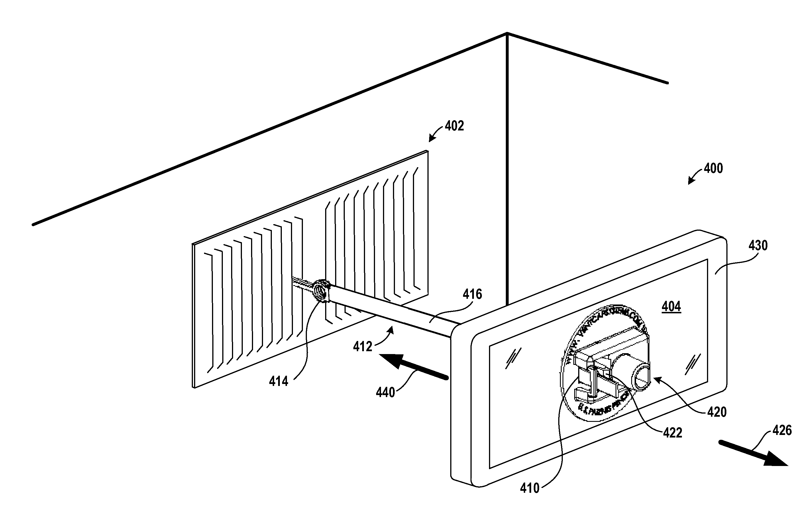
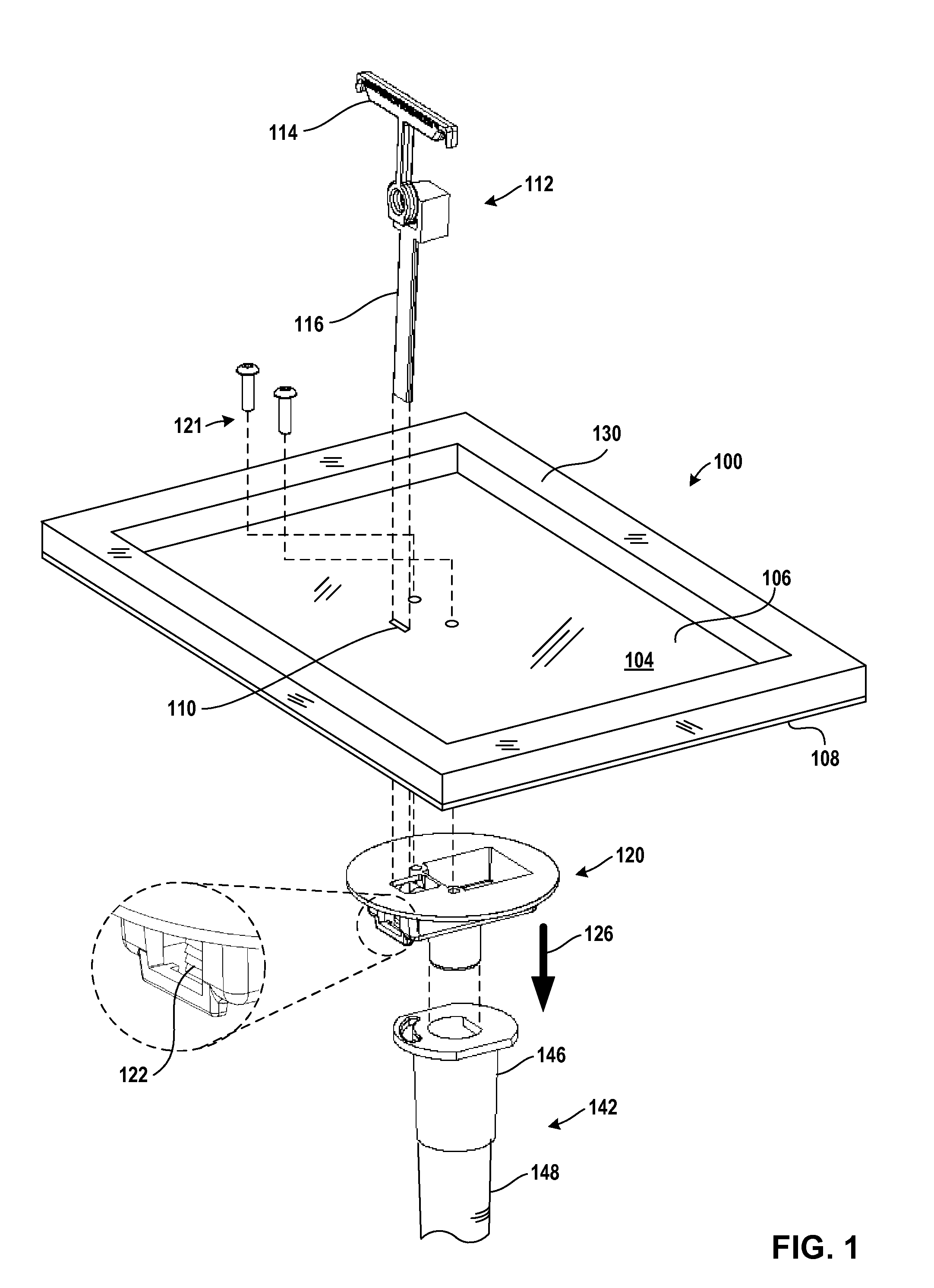
[0033]Exemplary embodiments of air duct blocking devices for obstructing airflow through portions of an air duct system are described herein with reference to the accompanying drawings, beginning with FIG. 1. FIG. 1 sets forth a drawing illustrating a perspective, exploded view of an exemplary removable air duct sealing system (100) for obstructing airflow through portions of an air duct system according to embodiments of the present invention. Air duct systems are used in heating, ventilation, and air conditioning (HVAC) to deliver, circulate, or remove air using supply, return, or exhaust airflows. Air duct systems, therefore, are one method of ensuring acceptable indoor air quality as well as thermal comfort.

[0034]Though air duct systems vary from one installation to another, many air duct system share a common set of components. Air duct systems generally include an air handler unit that may be composed of a blower or fan, heating or cooling elements, filters, humidifier, mixing...


PUM


Abstract

The present invention discloses removable air duct sealing systems for obstructing and directing airflow through portions of an air duct system. Some systems include a support plate having an opening and a flexible connector having a catch and a tail, the catch for connecting the connector to an air duct system component and the tail for passing through the opening in the support plate. Some systems include a fastener connected to the support plate, the fastener being capable of interacting with the connector in dependence upon the positioning of the fastener. In some systems, the fastener has a catch capable of being configured in a position that prevents the fastener from moving in a direction relative to the flexible connector but will allow the fastener to move in another direction. Some systems also include a gasket for restricting airflow when the gasket is pressed toward the air duct system component.

Description

[0001]This application claims the benefit of and is a continuation-in-part of Non-Provisional application Ser. No. 12 / 757,397 entitled “Air Vent Cover For Use In Testing Air Leakage Of An Air Duct System” and filed on Apr. 9, 2010, which is incorporated herein by reference in its entirety.[0002]This application claims the benefit of and is a continuation-in-part of Non-Provisional application Ser. No. 13 / 108,957 entitled “Air Duct Blocking Device For Obstructing Airflow Through Portions Of An Air Duct System” and filed on May 16, 2011, which is incorporated herein by reference in its entirety.TECHNICAL FIELD[0003]The present invention relates to the field of removable air duct sealing systems for obstructing or directing airflow through portions of an air duct system.BACKGROUND ART[0004]As the trend to conserve energy continues, more individuals are demanding and more governmental entities are mandating that houses and commercial facilities undergo periodic energy audits. An energy ...

Claims


Application Information

Patent Timeline
IPC IPC(8): F24F11/02F24F13/20
CPCF24F13/20F24F13/082F24F13/072Y10T24/1498
Inventor BREED, RICHARD COREY
Owner BREED RICHARD COREY
Why Eureka
Try Eureka