Shock attenuator and closure for same

a technology of shock attenuator and closure, which is applied in the direction of mechanical equipment, metal working equipment, pipe elements, etc., can solve the problems of fatigue loading, failure of the closure, and force requirements, and achieve the effect of reducing the number of failures

Inactive Publication Date: 2014-08-14
JOHNSTON CHARLES E
View PDF7 Cites 2 Cited by
  • Summary
  • Abstract
  • Description
  • Claims
  • Application Information

AI Technical Summary

Benefits of technology

[0009]A shock attenuator capable for use with a high pressure fluid line at pressures experienced by waterjet cutting systems comprises an attenuator body having an internal generally axially-extending bore extending between end regions, at least one of which is open-ended. An end plug is disposed within the open-ended region of the bore to seal the bore. The end plug has a though-hole for accommodating a fitting in fluid communication between the bore and a high pressure fluid line. A closure assembly retains the end plug within the bore, and includes a first plurality of generally radially-extending tabs extending fro

Problems solved by technology

This presents a twofold problem: first, the strength requirements due to the straight force loading the closure system and, second, the fatigue loading due to the cycling of the attenuator system, typically 10 to 50 times a day.
At the very high working pressures to which these attenuator systems are subjected, failure of the closures can have devastating consequences.
The use of screw-in type closure plugs present design problems which, to overcome, are expensive to manufacture.
Improper designs can result, and in fact have resulted, in catastrophic failures of the closure system.
An example of a catastrophic failure is where the seal material sealing the closure member to the attenuator body migrates into the thread area, increasing the load on the threads due to the thread's resulting maximum diameter being greater than the original (typically, 2.375 inch (6 cm)) se

Method used


Image

  • Shock attenuator and closure for same
  • Shock attenuator and closure for same
  • Shock attenuator and closure for same

Examples


Embodiment Construction

[0023]As will be clear below, there are alternative configurations of a preferred attenuators constructed in accordance with the invention. One alternative will be referred to below as the externally locked” configuration, and the other will be referred to as the “internally locked” configuration.

Externally Locked Configuration

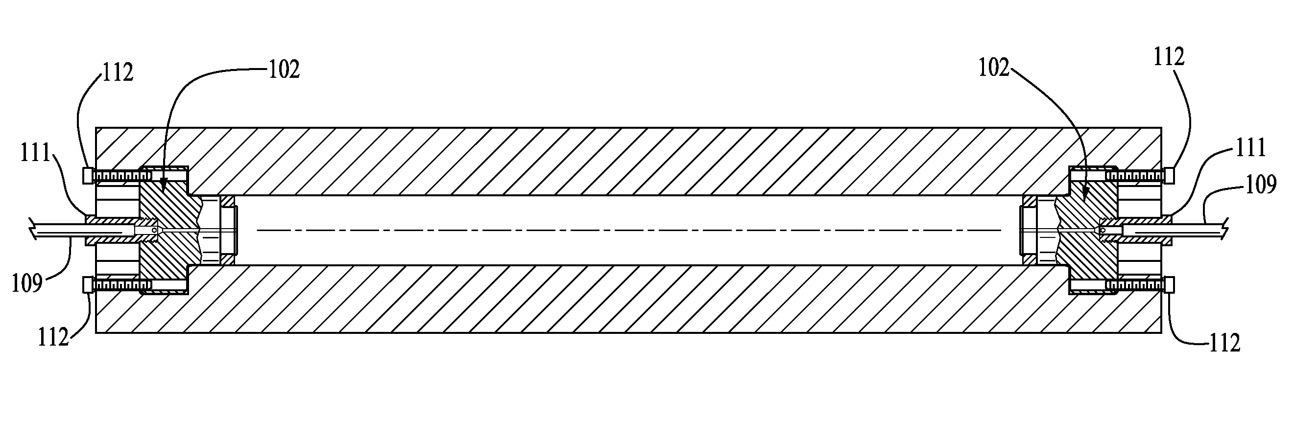
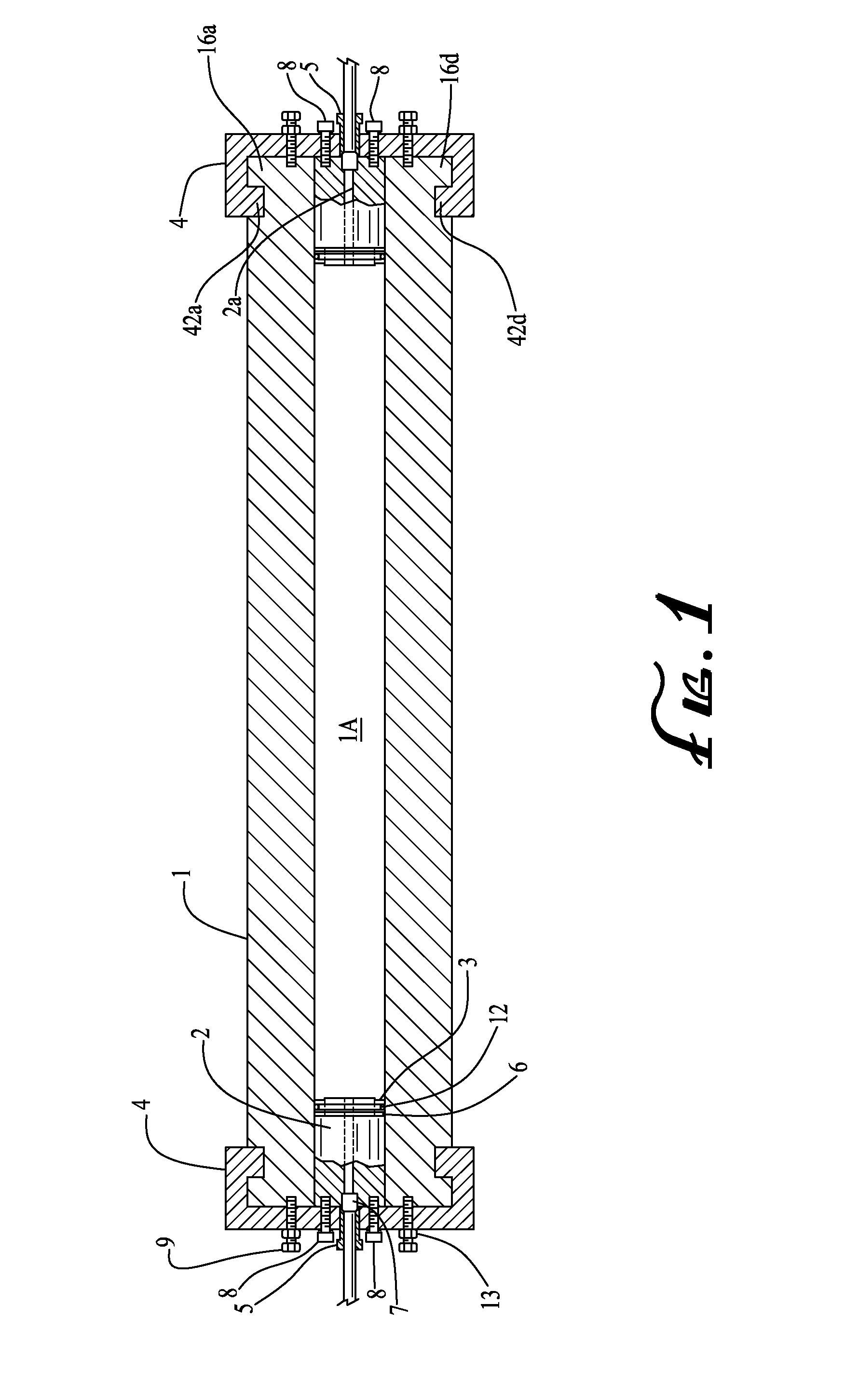
[0024]FIG. 1 shows a preferred attenuator body 1 having an internal bore 1A communicating between opposing ends. Male end plugs 2 are installed at those opposite ends of the body to close the bore.

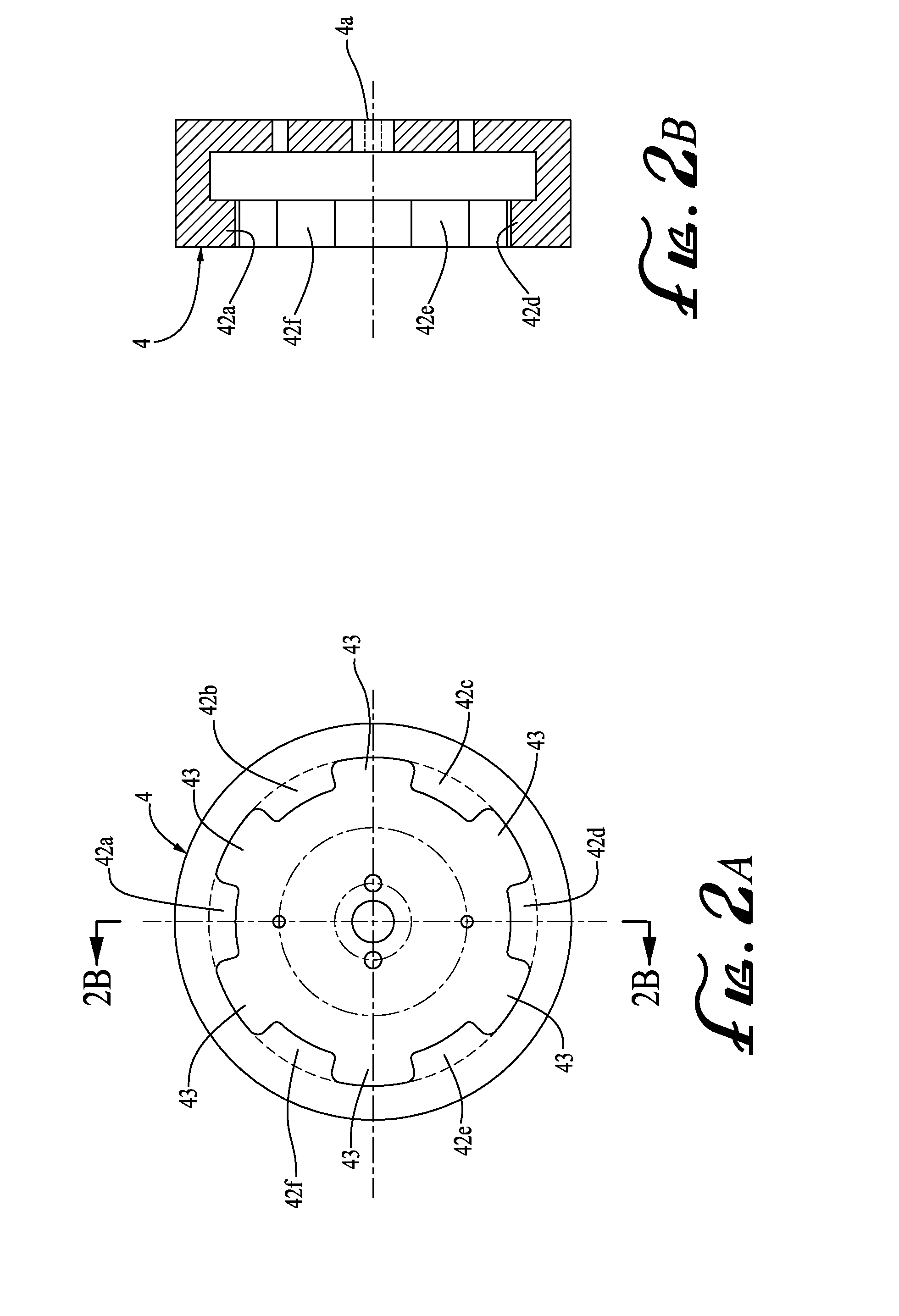
[0025]The attenuator body is closed at each end by a respective end cap 4 having a through-hole 4A through which fluid communication with the bore is enabled via a fitting hereinafter described. The fitting at each end permits the ingress of fluid at one end of the attenuator body (the “inlet”) and the egress of fluid at the other end (the “outlet”). It may be noted, and it is known to those of ordinary skill in the art, that the fluid does not necessarily flow thro...


PUM


Abstract

A shock attenuator capable for use with a high pressure fluid line at pressures experienced by waterjet cutting systems comprises an attenuator body having an internal generally axially-extending bore extending between end regions, at least one of which is open-ended. An end plug within the open-ended region of the bore seals the bore and has a though hole for accommodating a fitting for connection to a high pressure fluid line. A closure assembly for retaining the end plug within the bore includes a first plurality of generally radially-extending tabs extending from the attenuator body and circumferentially disposed about said axis, with each of said tabs of the first plurality being separated from the next tab by a respective gap. A second plurality of generally radially-extending tabs is coupled to the end plug and circumferentially disposed about said axis, with each of said tabs also being separated from the next tab by a respective gap. The second plurality of tabs is positioned for retention by said first plurality of tabs in such a way that the end plug is retained in the bore when subjected to the high pressure from high pressure fluid within the bore.
In one embodiment, the first plurality of tabs extends outward from the body's exterior to engage the second plurality of tabs extending inwardly from an end cap.
In another embodiment, the first plurality of tabs extends inwardly from the bore's wall to engage a second plurality of tabs extending outwardly from the end plug.

Description

PRIORITY CLAIM AND INCORPORATION BY REFERENCE [0001]This application claims priority of U.S. Provisional Patent Application 61 / 539,775 filed Sep. 27, 2011, the content of which is hereby incorporated by reference.BACKGROUND [0002]Shock attenuators are employed in ultra-high pressure waterjet cutting systems to smooth the unwanted pressure excursions caused by the reciprocating operation of the system's intensifier. These systems are typically operated to pressures in the 90,000 PSI (620,528 kPa) range, with the typical need for a minimum volume of 1.5 liters but a preferred volume of 2 liters to optimize the attenuator's effectiveness. As used herein, the term “waterjet cutting system” shall include abrasivejet cutting systems wherein abrasive is entrained into the waterjet.[0003]The most economical design has been to use a heavy walled tubular container with a typical inside diameter of 2.375 inches (6 cm) and wetted area of 29 inches (187 cm) or greater. These parameters yield a 2...

Claims


Application Information

Patent Timeline
IPC IPC(8): F16L55/05
CPCB26F3/004B26F2003/006F16L55/05
Inventor JOHNSTON, CHARLES E.
Owner JOHNSTON CHARLES E
Why Eureka
Try Eureka