Input tools having viobro-acoustically distinct regions and computing device for use with the same

a technology of vibroacoustic regions and input tools, which is applied in the field of passive input tools, can solve problems such as more complex manufacturing

Active Publication Date: 2014-08-28
QEEXO
View PDF6 Cites 35 Cited by
  • Summary
  • Abstract
  • Description
  • Claims
  • Application Information

AI Technical Summary

Benefits of technology

This patent describes a technology that allows for precise detection and identification of different parts of a device through their unique sound patterns generated when they are in contact with surfaces. The technology includes a touch screen, special tools designed to produce specific sounds when pressed on the screen, and sensors that can identify these individual sounds. Overall, this system provides better accuracy and efficiency than traditional methods of interacting with devices.

Problems solved by technology

The technical problem addressed in this patent is how to create a passive input tool that does not require any electronic components such as direct current sources, battery packs, or even integrated circuits.

Method used


Image

  • Input tools having viobro-acoustically distinct regions and computing device for use with the same
  • Input tools having viobro-acoustically distinct regions and computing device for use with the same
  • Input tools having viobro-acoustically distinct regions and computing device for use with the same

Examples


Embodiment Construction

[0013]The advantages and features of exemplary embodiments and methods of accomplishing these will be clearly understood from the following embodiments taken in conjunction with the accompanying drawings. However, the exemplary embodiments are not limited and may be implemented in various forms. It should be noted that the present embodiments are provided to make a full disclosure and also to allow those skilled in the art to understand the full range of the exemplary embodiments. Therefore, the exemplary embodiments are to be defined only by the scope of the appended claims.

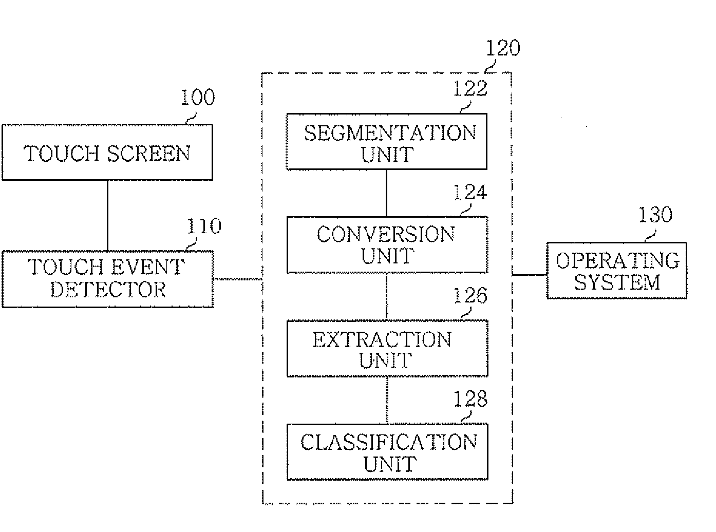
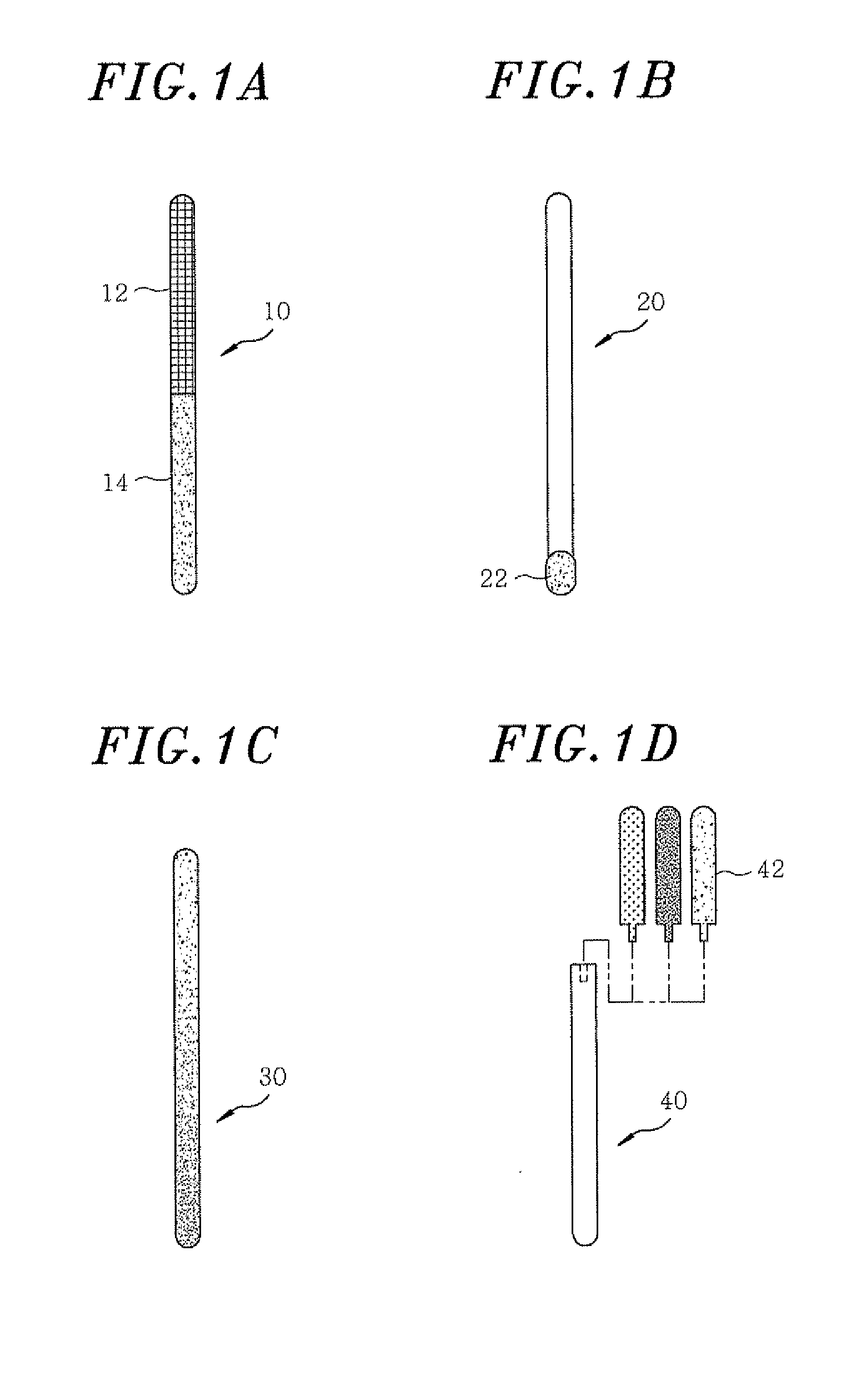
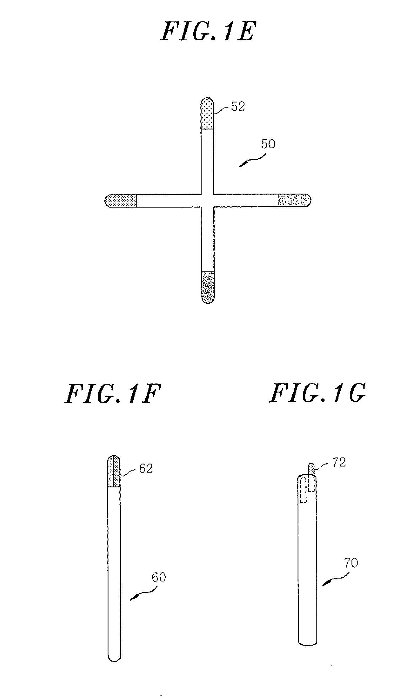
[0014]FIGS. 1A to 1G illustrate a variety of input tools with vibro-acoustically distinct regions that interact with a touch screen in accordance with embodiments of the present invention.

[0015]In general, a touch screen is an electronic visual display that a user can control through single or multi-touch gestures by touching the screen with one or more fingers. Some touch screens can also detect an object such ...


PUM


Abstract

An input tool includes a body in the form of a stylus with plurality of vibro-acoustically distinct regions. The vibro-acoustically distinct regions produce vibro-acoustic responses when the regions touch the surface of the touch screen. The vibro-acoustic responses are used in a computing device to detect what region of the input tool was used.

Description


Claims


Application Information

Patent Timeline
Owner QEEXO
Why Eureka
Try Eureka