

Protective enclosure for touch screen device
a technology for protecting enclosures and touch screens, which is applied in the direction of portable computer details, electric apparatus casings/cabinets/drawers, instruments, etc., can solve the problems of damage to the portable electronic device through rough handling and dropping, damage to the portable electronic device through damage or destruction, and achieve the effect of preventing damage to the touch screen
- Summary
- Abstract
- Description
- Claims
- Application Information
AI Technical Summary
Benefits of technology
Problems solved by technology
Method used
Image

Examples
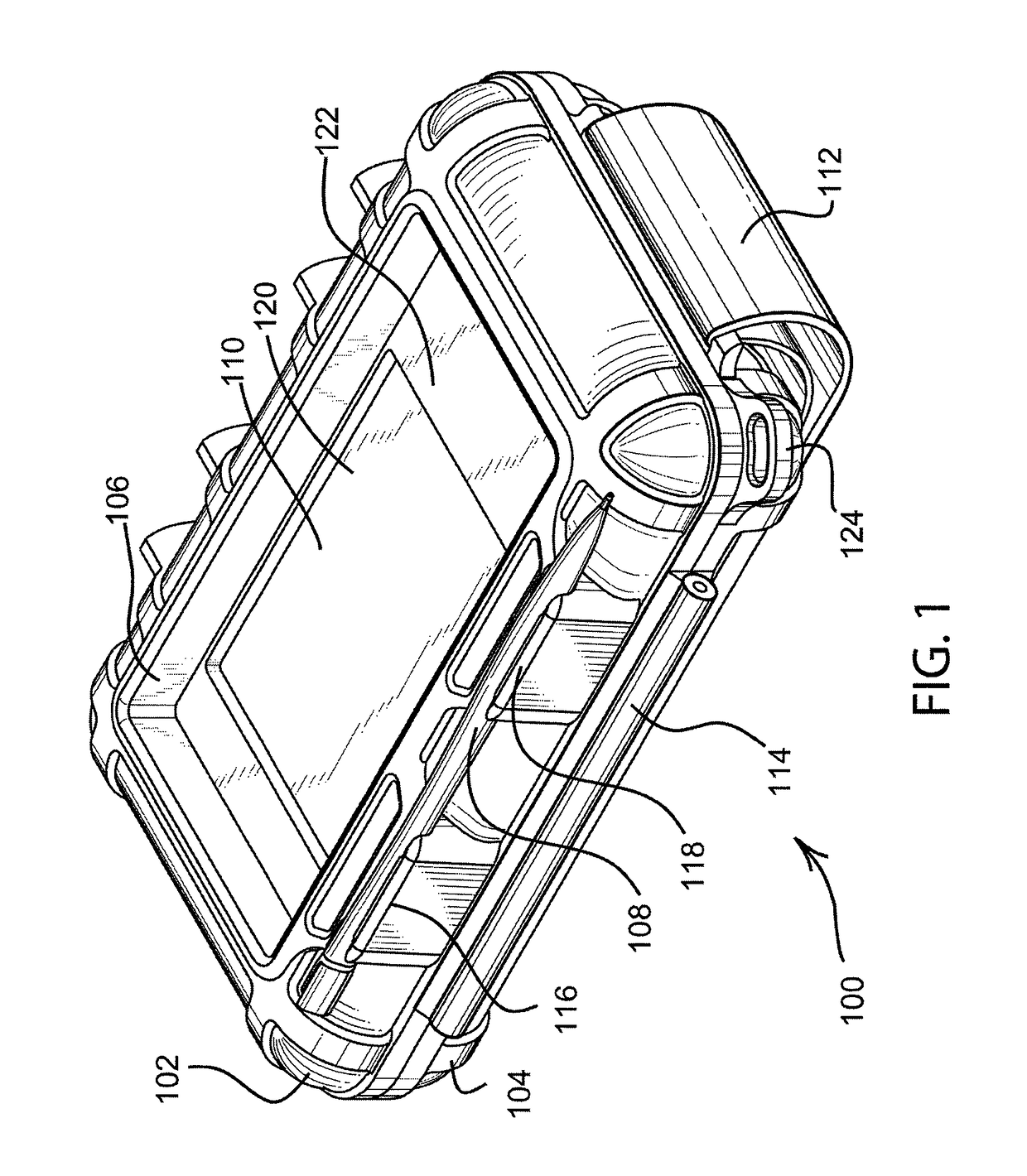
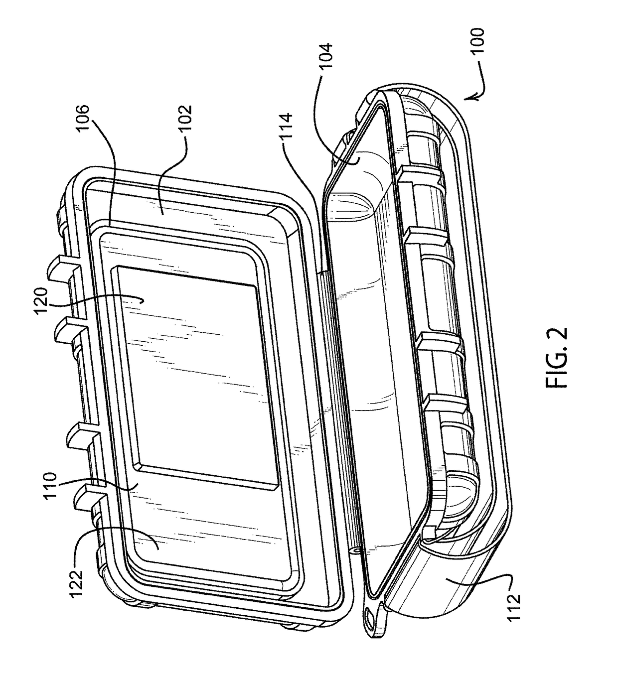
case 100
[0042]Protective case 100 is designed to hold a personal electronic device, such as a personal data assistant, a computer, including laptops, handheld and ultramobile computers and tablet computers, MP3 players, music players, video players, smart phones, GPS navigational devices, telematics devices, cell phones, satellite phones, pagers, monitors, walkie-talkies, bar code scanners, etc. that are used for a wide variety of purposes. As used herein, the term “personal electronic device” can include anyone of these devices, or similar devices. A personal electronic device, such as a Palm Pilot, Handspring Visor, Compaq Ipaq, Hewlett Packard Jornada, iPod®, iPhone®, and similar products use a touch screen for display and data entry. The touch screen display comprises either a color or black and white liquid crystal display with a touch sensitive device for activating the device. The display is used for displaying graphics, text, and other information to the user. The touch screen can b...
embodiment 100
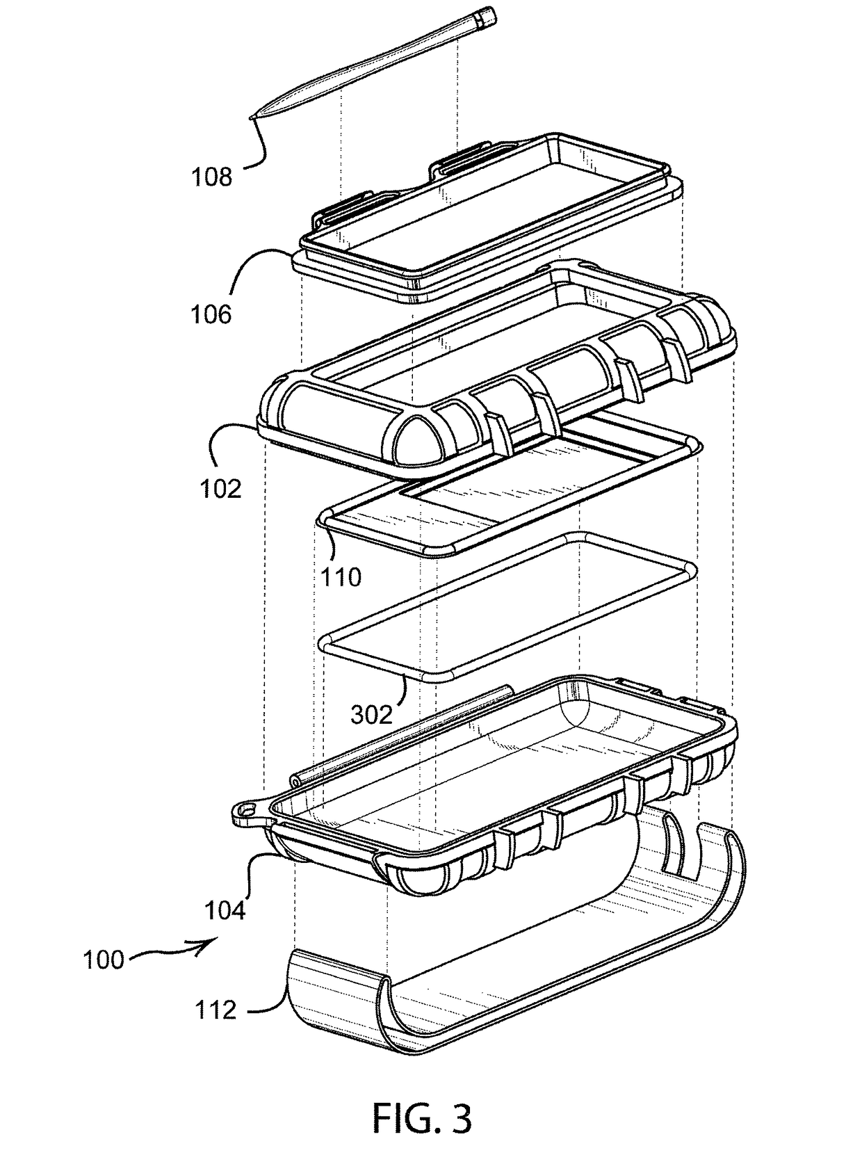
[0060]FIG. 3 illustrates a perspective view of the embodiment 100 shown in an exploded state. The hand strap 112 attaches to the rear cover 104. The overmolded grommet 106 holds the stylus 108 and is attached to front cover 102. The membrane 110 attaches to the grommet 106 and is held in place with an o-ring 302.
[0061]FIG. 4 illustrates a perspective view of the embodiment 100 shown from the rear. The hand strap 112 is shown, along with rear cover 104 and front cover 102. The stylus 108 is shown inserted into the overmolded grommet 106.
[0062]FIG. 5 illustrates a top view of the embodiment 100. The front cover 102, membrane 110, stylus 108, and hinge 114 are all visible.
[0063]FIG. 6 illustrates a section view of the embodiment 100 taken through the section line shown in FIG. 5. The front cover 102, rear cover 104, overmolded gasket 106, stylus 108, membrane 110, hand strap 112, and o-ring 302 are all shown hatched in this view.
[0064]FIG. 7 illustrates a detail view of Section B of th...
embodiment 800
[0078]FIG. 8 is an illustration of embodiment 800 of the present invention wherein the personal electronic device 802 is encapsulated by a protective cover 804. The installation of the personal electronic device 802 is accomplished by sliding personal electronic device 802 into the opening 808, then folding door 806 closed and securing flap 810, which is hinged along line 812. Areas 814 and 816 may comprise a hook and loop fastener system or other fastening device. Recessed area 818 is adapted to fit against touch screen 820 of personal electronic device 802.
[0079]Embodiment 800 may be comprised of a single molded plastic part that may be very low cost. As shown, embodiment 800 may not be completely weathertight, since the door 806 does not completely seal the enclosure. However, such an embodiment may afford considerable protection to the personal electronic device 802 in the areas of dust protection, scratch protection, and being occasionally rained upon. Further, the low cost of ...
PUM
| Property | Measurement | Unit |
|---|---|---|
| thickness | aaaaa | aaaaa |
| thickness | aaaaa | aaaaa |
| thickness | aaaaa | aaaaa |
Abstract
Description
Claims
Application Information