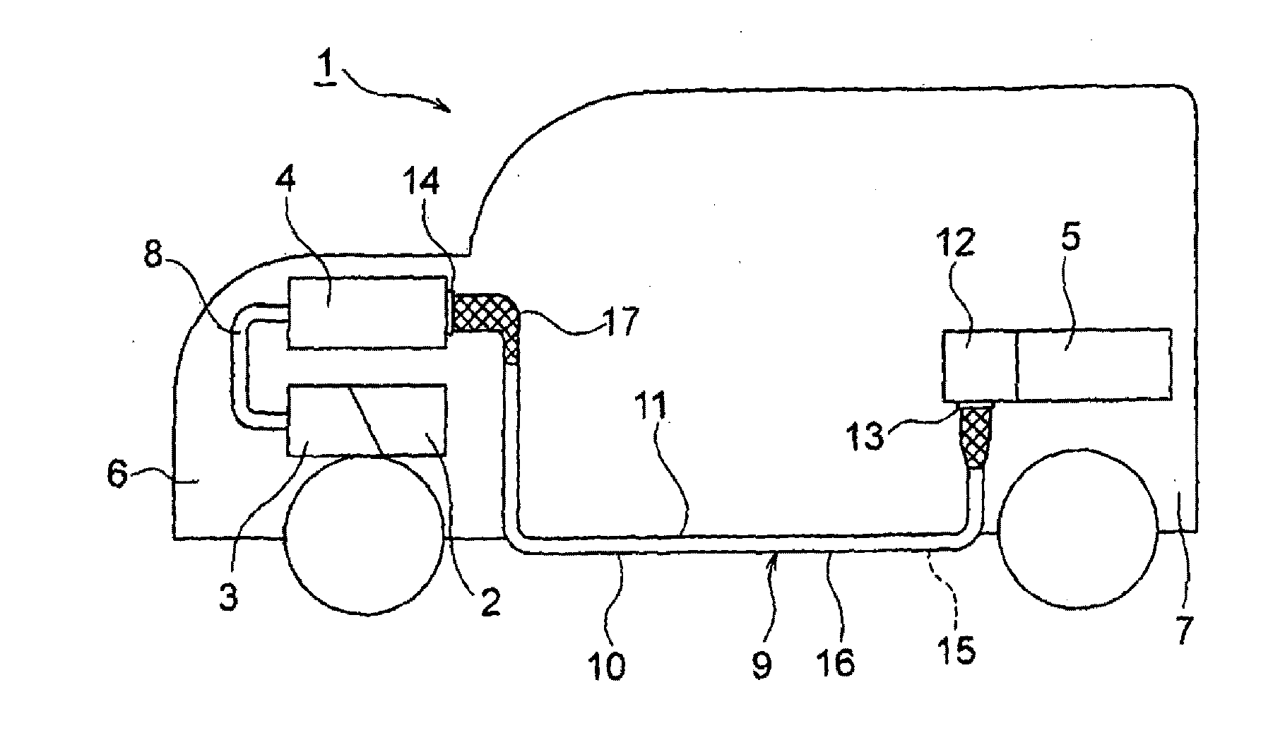
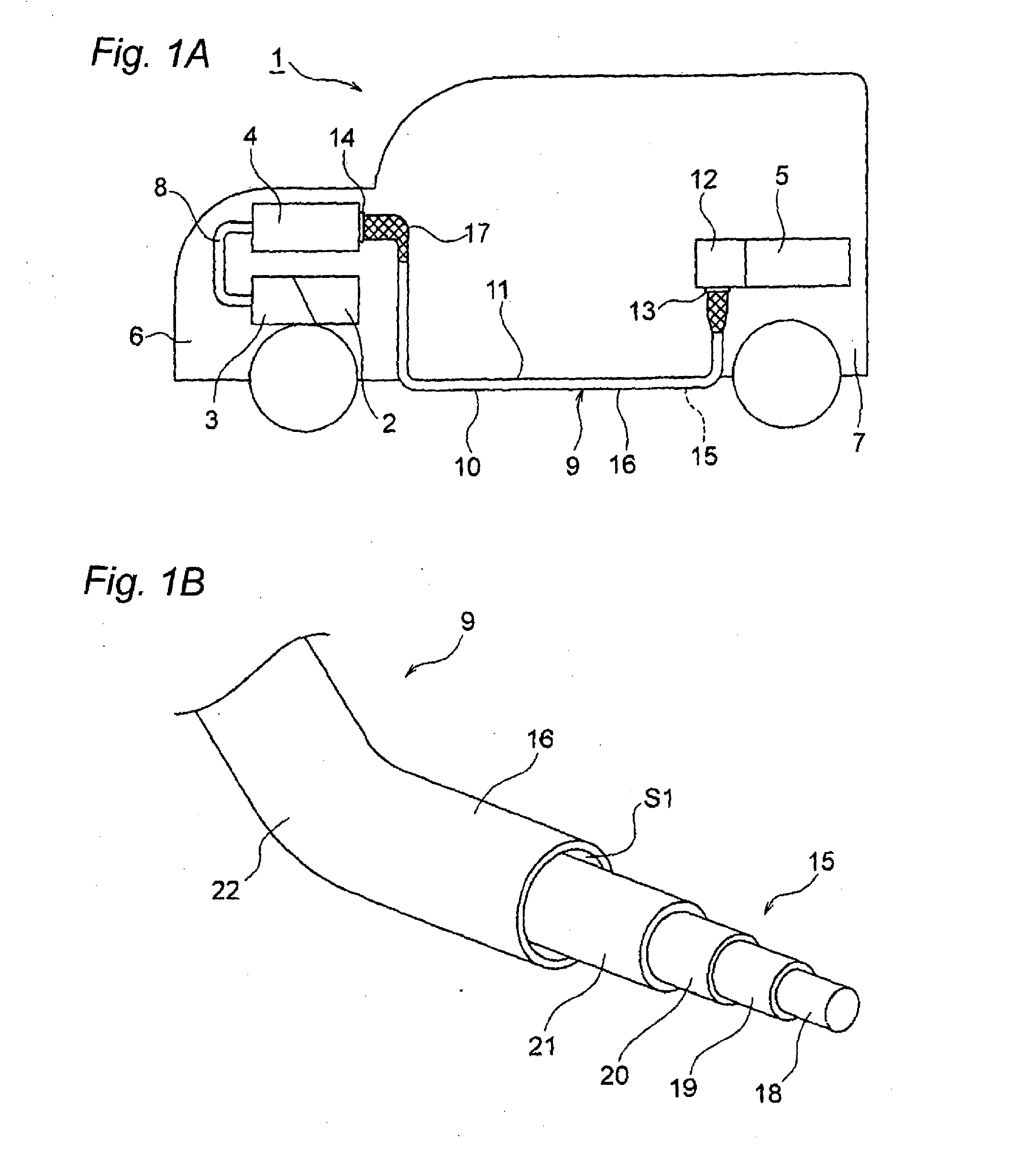
Wire harness

a wire harness and wire technology, applied in the direction of insulated conductors, cables, conductors, etc., can solve the problems of wire harness damage, thick conductor paths,

Active Publication Date: 2014-09-04
YAZAKI CORP
View PDF4 Cites 12 Cited by
  • Summary
  • Abstract
  • Description
  • Claims
  • Application Information

AI Technical Summary

Benefits of technology

[0010]According to one advantage of the invention, there is provided a wire harness, comprising:
[0011]a coaxial conducting wire including a plurality of high voltage paths which are coaxially aligned; and
[0012]an covering member, accommodating the coaxial conducting wire.
[0013]The coaxial conducting wire may further include a shield member that is formed by metal and is coaxial to and disposed outside the plurality of high voltage paths.
[0014]The covering member may be formed from a metal tubular body covering the coaxial conducting wire or a resin tubular body covering the coaxial conducting wire.
[0015]The covering member may have a bend pipe portion configured to be bent during routing and a non-bend pipe portion continued to the bend pipe portion and configured not to be bent during routing.

Problems solved by technology

Since the conducting paths supply electrical power for a drive system, the conducting paths become thick.
Then the wire harness may be damaged or the like.

Method used


Image

  • Wire harness
  • Wire harness
  • Wire harness

Examples


first embodiment

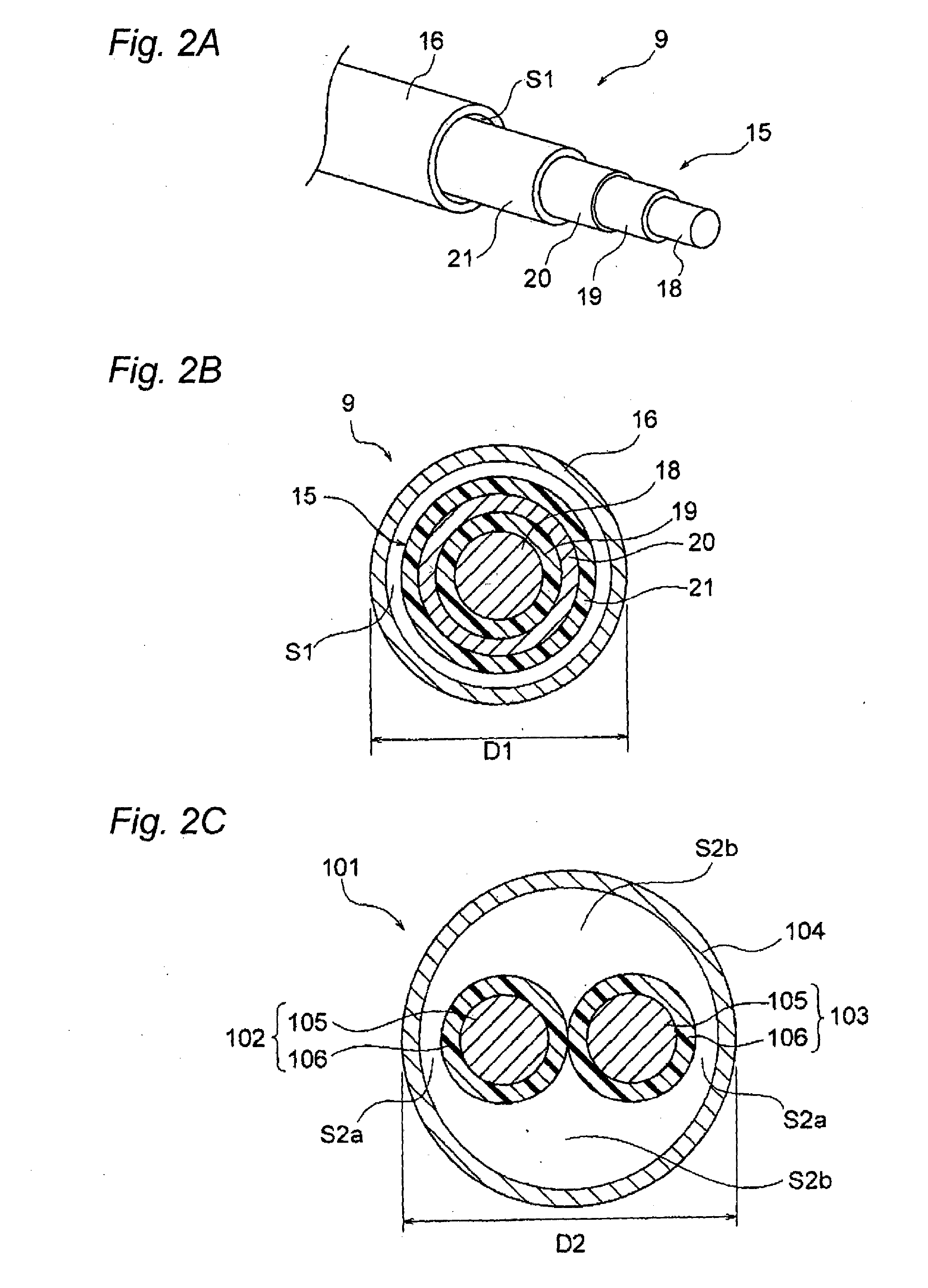
[0076]In FIGS. 3A to 3B, a wire harness 31 is a high voltage member and includes a coaxial conducting wire 32 and an covering member 33. Although unillustrated, the electromagnetic shield member is assumed to be identical with; for instance, the electromagnetic shield member described in connection with the

[0077]The coaxial conducting wire 32 is configured so as to include three paths (triple circuitry) in the form of a single wire. Specifically, the coaxial conducting wire 32 includes a first conducting path 34 that is situated at a center of the coaxial conducting wire 32 and that assumes a circular cross sectional profile; a first insulator 35 that sheathes an outer periphery of the first conducting path 34 in a predetermined thickness; a second conducting path 36 laid outside the first insulator 35; a second insulator 37 that sheathes an outer periphery of the second conducting path 36 in a predetermined thickness; a third conducting path 38 laid outside the second insulator 37;...

third embodiment

[0093]A third embodiment is hereunder described by reference to the drawings. FIGS. 4A to 4C are schematic illustrations of a wire harness that is to be still another example.

[0094]In FIG. 4A, a wire harness 51 is a high voltage member and includes the electromagnetic shield member 17, a coaxial conducting wire 52, and an covering member 53.

[0095]The coaxial conducting wire 52 is configured so as to include two paths (double circuitry) in the form of a single wire. The coaxial conducting wire 52 is also configured in such a way that the electromagnetic shield member 17 coaxial to the two circuits is disposed outside the two circuits. Specifically, the coaxial conducting wire 52 is configured by inclusion of the first conducting path 18 that is situated at the center of the coaxial conducting wire 52 and that has a circular cross sectional profile, the first insulator 19 that sheathes the outer periphery of the first conducting path 18 in a predetermined thickness, the second conduct...

fourth embodiment

[0107]A fourth embodiment is hereunder described by reference to the drawings. FIGS. 5A to 5C are schematic illustrations of a wire harness that is to be an exemplary modification of the wire harness shown in FIGS. 4A to 4C.

[0108]In FIG. 5A, a wire harness 71 is materialized by making a change to the covering member of the wire harness 51 of the third embodiment. Specifically, the wire harness 71 is configured by inclusion of the coaxial conducting wire 52 in close contact with the exterior surface of the second insulator 21 and a covering member 72.

[0109]The covering member 72 is a tubular body made of a resin, or a resin tubular body, and formed so as to assume a length required to accommodate the coaxial conducting wire 52 and a thickness required to protect the coaxial conducting wire 52. The covering member 72 is formed so as to assume a circular cross sectional profile. The cross sectional profile is a mere example and may also be an ellipsoidal shape, an oval shape, or a rect...


PUM


Abstract

A wire harness includes a coaxial conducting wire including a plurality of high voltage paths which are coaxially aligned, a covering member, accommodating the coaxial conducting wire, and a terminal, connected to one of the high voltage paths disposed outside of another one of the high voltage paths, and including a tubular portion coaxial to the coaxial conducting wire. The terminal includes a connection tubular portion as the tubular portion, a crimping tubular portion connecting the one of the high voltage paths to the connection tubular portion by crimping, and an outside connection terminal integrated with the connection tubular portion.

Description

CROSS REFERENCE TO RELATED APPLICATIONS[0001]This application is a continuation of PCT application No. PCT / JP / 2012 / 080806, which was filed on Dec. 21, 2012 based on Japanese Patent Application Nos. 2011-253419 filed on Nov. 21, 2011, and 2012-131505 filed on Jun. 11, 2012, the contents of which are incorporated herein by reference.BACKGROUND OF THE INVENTION[0002]1. Field of the Invention[0003]The invention is related to a wire harness.[0004]2. Description of the Related Art[0005]A high voltage wire harness has been used for electrically connecting; for instance, a battery to an inverter unit, in a hybrid automobile or a pure electric vehicle. The wire harness for connecting the battery to the inverter unit includes two high voltage conducting paths, which are a plus circuit and a minus circuit respectively, and a covering member for protecting them.[0006]When a metallic pipe disclosed in PTL 1 is adopted as the covering member, the two conducting paths are accommodated while arrang...

Claims


Application Information

Patent Timeline
Patent Type & Authority Applications(United States)
IPC IPC(8): B60R16/02
CPCB60R16/0215H01B9/04B60R16/0207H02G3/0481
Inventor ADACHI, HIDEOMIOZAKI, YOSHIAKIICHIKAWA, HIDEHIROTOHYAMA, EIICHI
Owner YAZAKI CORP
Why Eureka
Try Eureka