LED luminaire with improved thermal management and novel LED interconnecting architecture

a technology of led luminaires and led interconnections, applied in the direction of semiconductor devices, lighting and heating apparatus, lighting support devices, etc., can solve the problems of phosphor material degradation, heat retention may be an issue for a package, and optical loss may occur when the light is shining

Active Publication Date: 2014-09-18
IDEAL IND LIGHTING LLC
View PDF8 Cites 59 Cited by
  • Summary
  • Abstract
  • Description
  • Claims
  • Application Information

AI Technical Summary

Problems solved by technology

While the reflective cup may direct light in an upward direction, optical losses may occur when the light is reflected (i.e. some light may be absorbed by the reflector cup due to the less than 100% reflectivity of practical reflector surfaces).
In addition, heat retention may be an issue for a package, since it may be difficult to extract heat through the leads.
This elevated operating temperature can cause degradation of the phosphor material over time.
It can also cause a reduction in phosphor conversion efficiency and a shift in conversion color.
Some of these designs, however, do not provide optimized omnidirectional emission that fall within standard uniformity requirements.
Some of these bulbs also contain a large number of interconnected LEDs making them prohibitively complex, expensive and unreliable.
This makes these LED bulbs generally impractical for most illumination purposes.
This arrangement, however, does not provide omnidirectional emission patterns, but instead provides a pattern that is substantially forward biased.
The mesa for this bulb also comprises a hollow shell, which can limit its ability to thermally dissipate heat from the emitters.
This can limit the drive current that can be applied to the LEDs.
This design is also relatively complex, using several LEDs, and is not compatible with large volume manufacturing of low-cost LED bulbs.

Method used


Image

  • LED luminaire with improved thermal management and novel LED interconnecting architecture
  • LED luminaire with improved thermal management and novel LED interconnecting architecture
  • LED luminaire with improved thermal management and novel LED interconnecting architecture

Examples


Embodiment Construction

[0026]Embodiments of the present invention now will be described more fully hereinafter with reference to the accompanying drawings, in which embodiments of the invention are shown. This invention may, however, be embodied in many different forms and should not be construed as limited to the embodiments set forth herein. Rather, these embodiments are provided so that this disclosure will be thorough and complete, and will fully convey the scope of the invention to those skilled in the art. Like numbers refer to like elements throughout.

[0027]It will be understood that, although the terms first, second, etc. may be used herein to describe various elements, these elements should not be limited by these terms. These terms are only used to distinguish one element from another. For example, a first element could be termed a second element, and, similarly, a second element could be termed a first element, without departing from the scope of the present invention. As used herein, the term ...


PUM


Abstract

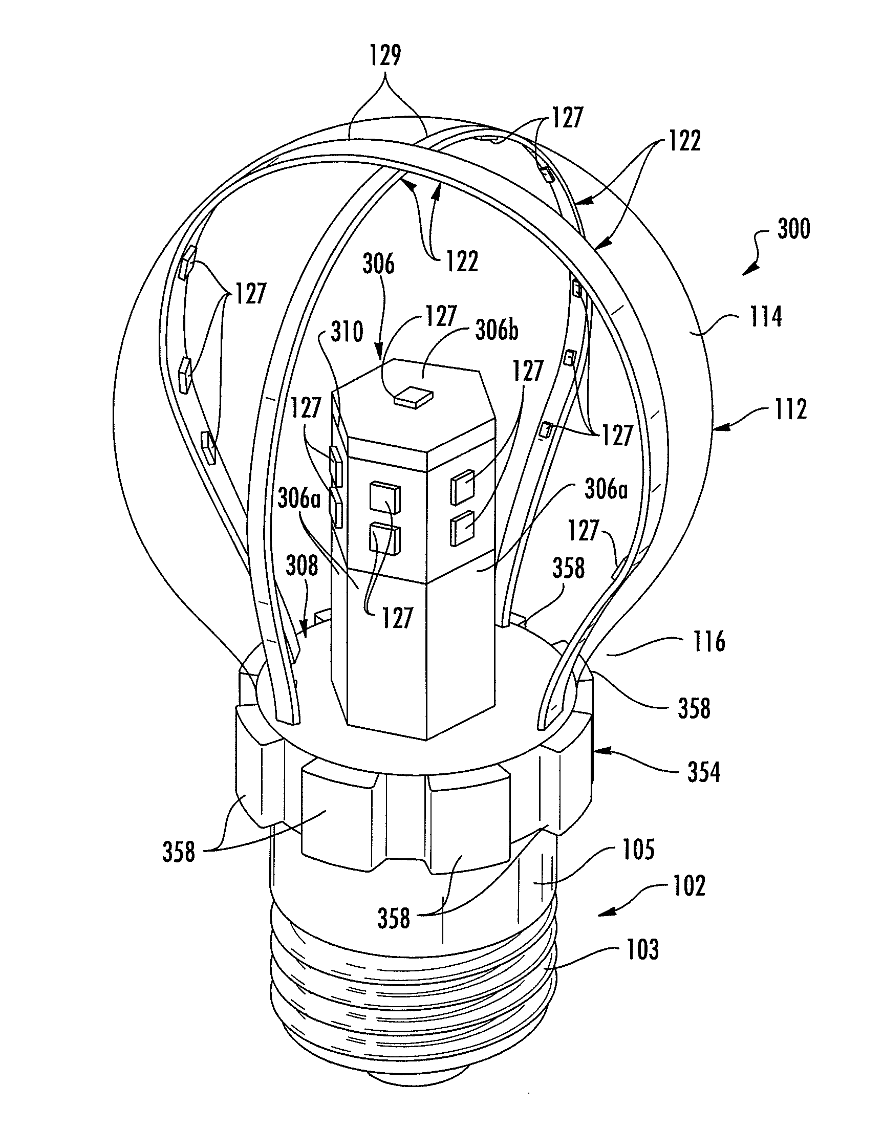
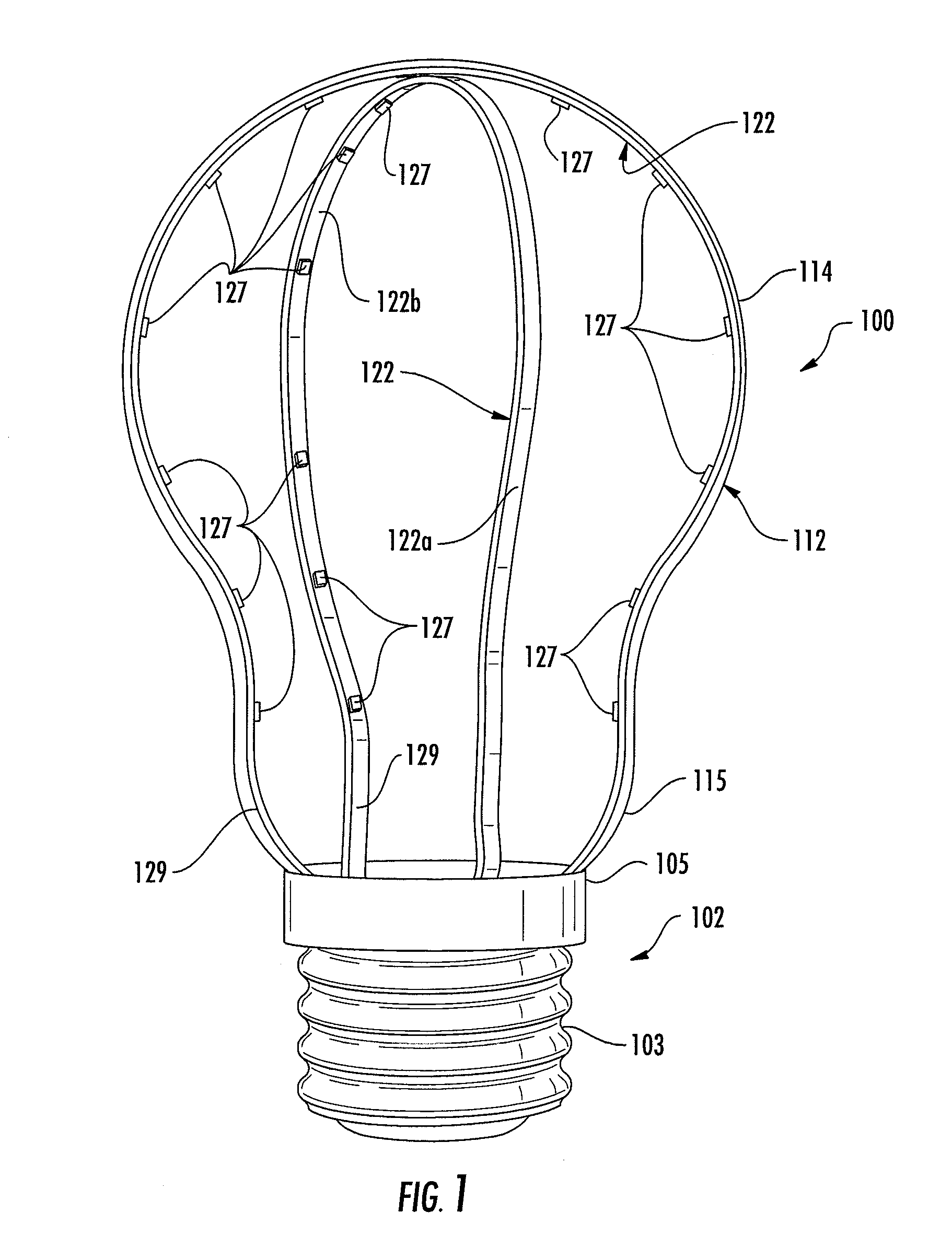
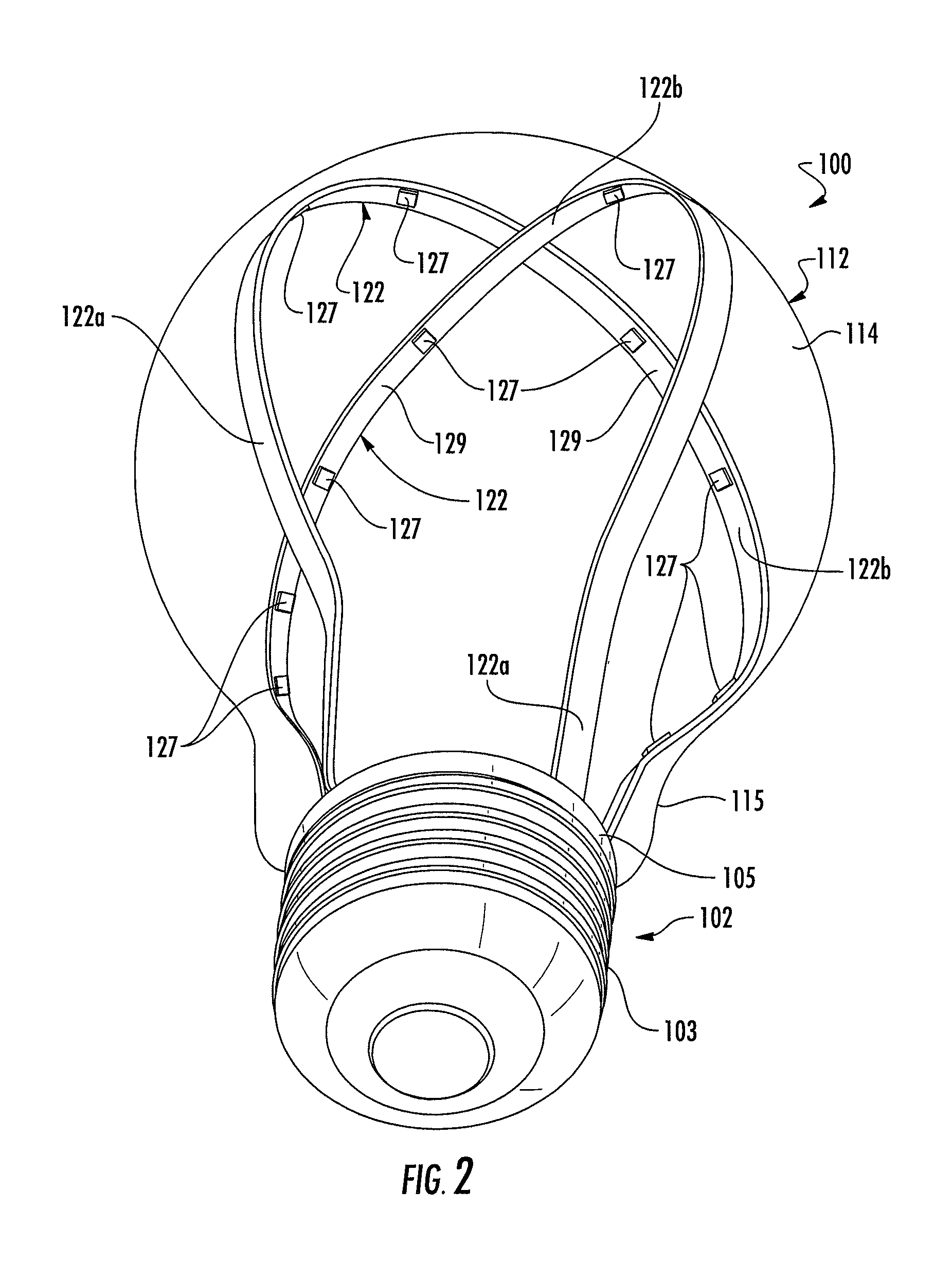
A LED lamp includes an optically transmissive enclosure and a base connected to the enclosure. LEDs are mounted on a ribbon for emitting light when energized though an electrical path from the base. The mounting ribbon for the LEDs has a surface that is positioned adjacent an interior surface of the enclosure for transmitting heat from the plurality of LEDs to the enclosure.

Description

[0001]This application claims benefit of priority under 35 U.S.C. §119(e) to the filing date of U.S. Provisional Application No. 61 / 802,079, as filed on Mar. 15, 2013, which is incorporated herein by reference in its entirety.BACKGROUND OF THE INVENTION[0002]1. Field of the Invention[0003]This invention relates to solid state lamps and bulbs and in particular to light emitting diode (LED) based lamps and bulbs capable of providing omnidirectional emission patterns similar to those of filament based light sources.[0004]2. Description of the Related Art[0005]Light emitting diodes (LED or LEDs) are solid state devices that convert electric energy to light, and generally comprise one or more active layers of semiconductor material sandwiched between oppositely doped layers. When a bias is applied across the doped layers, holes and electrons are injected into the active layer where they recombine to generate light. Light is emitted from the active layer and from all surfaces of the LED.[...

Claims


Application Information

Patent Timeline
Patent Type & Authority Applications(United States)
IPC IPC(8): F21K99/00
CPCF21K9/135F21K9/90F21V29/506F21V29/70F21K9/232F21K9/233F21Y2103/33F21Y2107/10F21Y2107/30F21Y2115/10
Inventor HEIKMAN, STEN
Owner IDEAL IND LIGHTING LLC
Why Eureka
Try Eureka