Service cable box

Active Publication Date: 2014-10-02
DIRTT ENVIRONMENTAL SOLUTIONS
View PDF10 Cites 9 Cited by
  • Summary
  • Abstract
  • Description
  • Claims
  • Application Information

AI Technical Summary

Benefits of technology

[0012]Implementations of the present invention overcome one or more of the foregoing or other problems in the art with systems and apparatus for securing and routing cables. In particular, one or more systems and apparatus provided herein include a service cable box that securely houses and allows efficient routing of cables. For instance, in one or more implementations the service cable box can include one or more chambers that organize, route, and secure cables. Additionally, the service cable box can include one or more securable doors, which can restrict access to the cables, for example, based on a user's clearance.
[0013]For example, an implementation of a service box includes a housing, a first connection chamber located within the housing, and a second connection chamber located within the housing. The service box further includes a connector module separating the first connection chamber from the first second connection chamber. The service box also includes a barrier plate coupled to the housing. The barrier plate has an opening. The barrier plate is sized and configured to at least partially cover the first connection chamber and to prevent access thereto. Additionally, the service box includes a door coupled to one or more of the housing and the barrier plate. The door is configured to slide open and selectively provide access to the second connection chamber through the opening in the front barrier plate. The service box also includes a lock configured to selectively lock the door relative to the barrier plate.
[0014]Another implementation of a service cable box includes a housing configured to be mounted within a wall. A connection chamber is disposed within the housing. The connection chamber is configured to physically secure secondary network cables. A front barrier plate is coupled to the housing. The front barrier plate includes at least one opening configured to provide access to the connection

Problems solved by technology

Depending on the design of a particular facility, accommodating separate cable boxes for each network can be difficult or impossible.
Unfortunately, including both data boxes and power or electrical boxes may increase installation and maintenanc

Method used


Image

  • Service cable box
  • Service cable box
  • Service cable box

Examples


Embodiment Construction

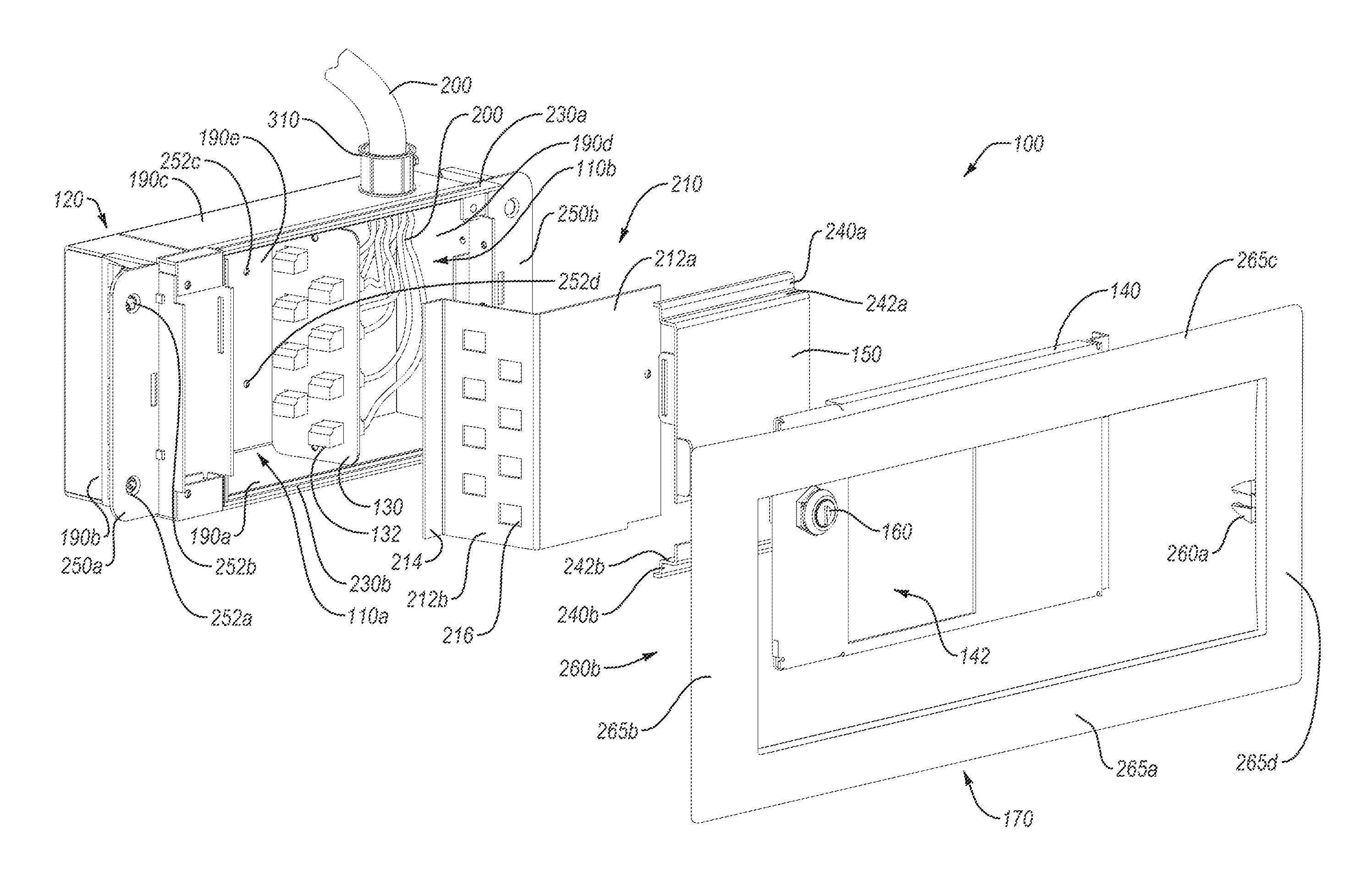
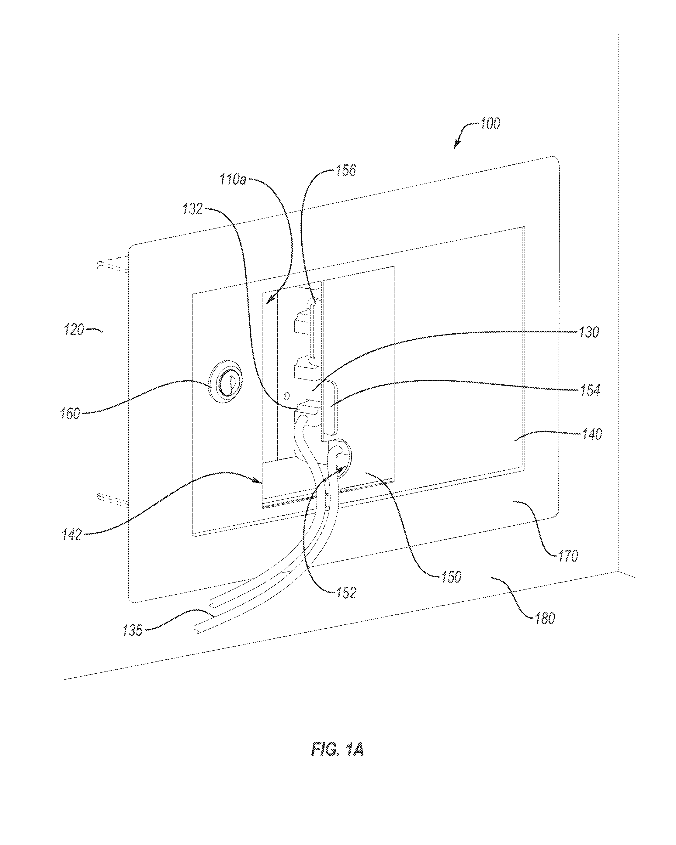
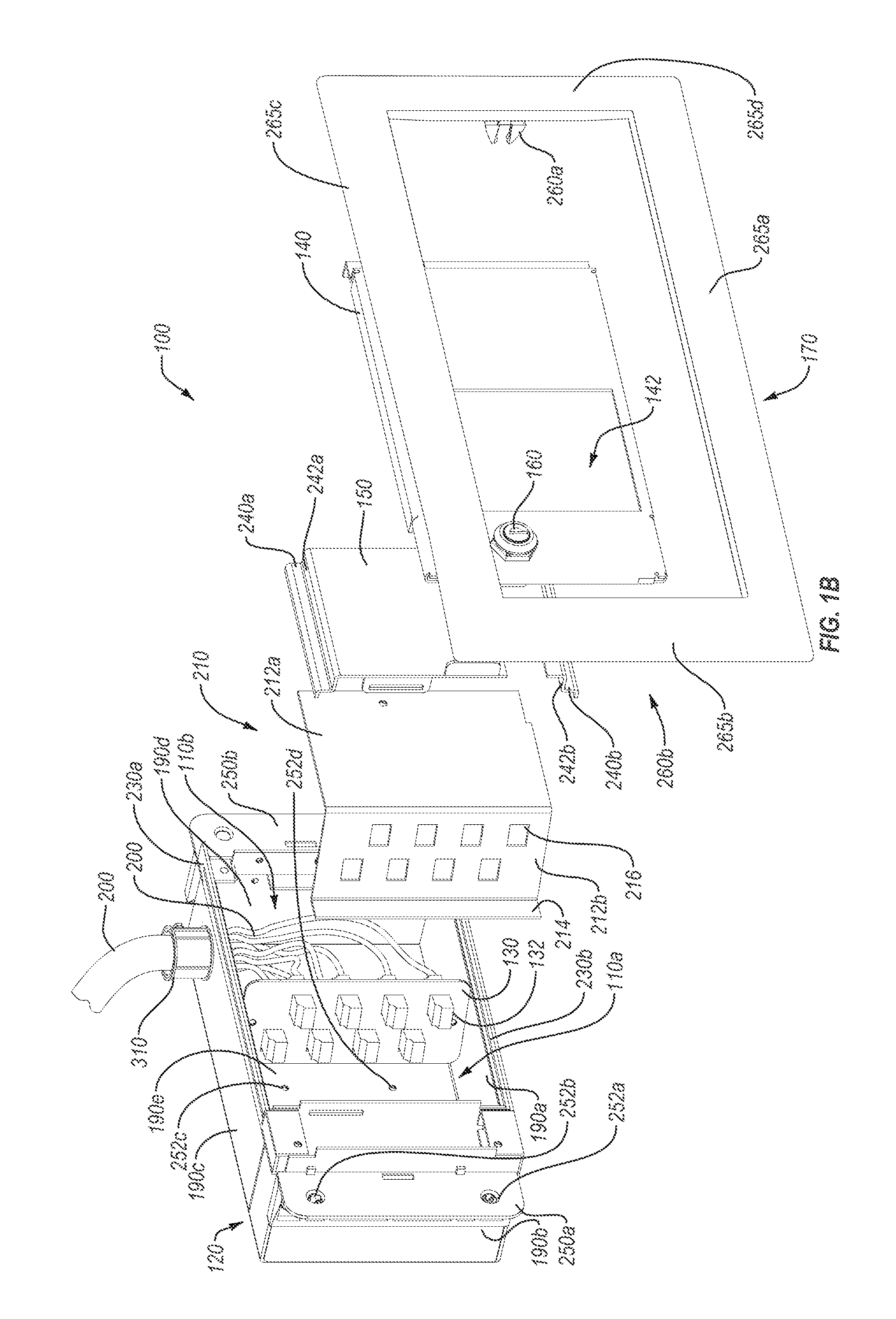
[0026]Implementations of the present invention include systems and apparatus for securing and routing cables. In particular, one or more systems and apparatus provided herein include a service cable box that securely houses and allows efficient routing of cables. For instance, in one or more implementations the service cable box can include one or more chambers that organize, route, and secure cables. Additionally, the service cable box can include one or more securable doors, which can restrict access to the cables, for example, based on a user's clearance.

[0027]More specifically, one or more implementations of a service cable box can secure certain network cables and / or connectors within secure connection chambers. The lockable doors can selectively close off the connection chambers. For example, a first lockable door may limit access for connecting to a network of a first security classification, while a second lockable door may limit access to connecting to a network having a se...


PUM


Abstract

Cables boxes and cable distribution systems securely store and route network cables of different types and/or security classifications. More specifically, a service cable box can include one or more chambers that can secure secondary network cables of one or more types and/or classifications. The service cable box can have secure and unsecure connection chambers. Accordingly, the service cable box can segregate network connections of different types and/or security classifications and can selectively provide secured access thereto.

Description

CROSS-REFERENCE TO RELATED APPLICATIONS[0001]The present invention is a 35 U.S.C. §371 U.S. National Stage of PCT Application No. PCT / US2012 / 065920 filed Nov. 19, 2012, entitled, “Service Cable Box,” which claims the benefit of priority to U.S. Provisional Application No. 61 / 570,714, filed Dec. 14, 2011, entitled “Secure Wall Cable Box.” The entire content of each of the aforementioned patent applications is incorporated herein by reference.BACKGROUND OF THE INVENTION[0002]1. The Field of the Invention[0003]This invention relates to systems, methods, and apparatus for securing network cabling and / or network or electrical connections at a network endpoint.[0004]2. Background and Relevant Art[0005]Security concerns in data and communication infrastructures have increased in importance as more individuals, businesses, government, and military organizations increase reliance on data and communication networks. As an example, both government and military agencies often require physical s...

Claims


Application Information

Patent Timeline
IPC IPC(8): H02G3/08
CPCH01R13/6397H02G3/086H02G3/08H02G3/18H02G3/14
Inventor ISAACKS, SCOTT J.MCCLOUD, SEAN C.KNOTT, JOSHUA RAY
Owner DIRTT ENVIRONMENTAL SOLUTIONS
Why Eureka
Try Eureka