Overvoltage protection device
- Summary
- Abstract
- Description
- Claims
- Application Information
AI Technical Summary
Benefits of technology
Problems solved by technology
Method used
Image

Examples
Embodiment Construction
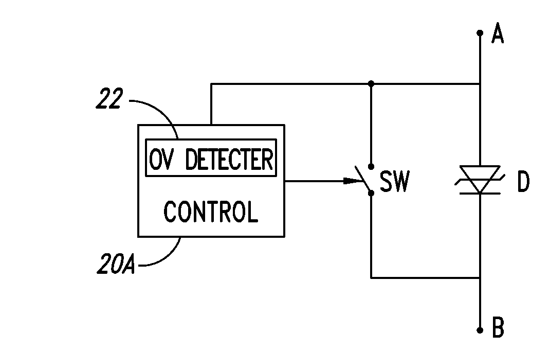
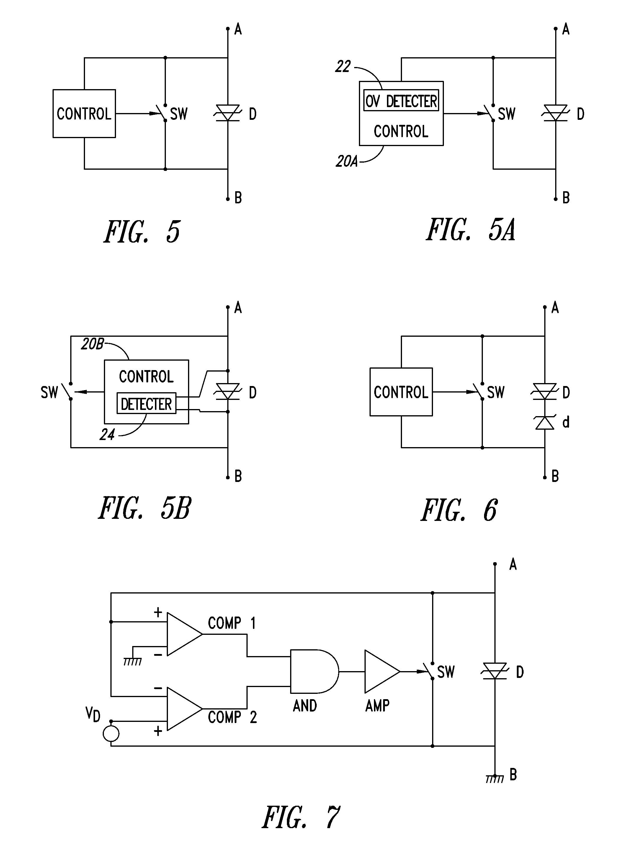
[0030]FIG. 5 shows a first embodiment of a protection device. This protection device comprises between two terminals A and B the parallel assembly of:
[0031]a break-over type protection diode D,
[0032]a switch SW, and
[0033]a circuit (CONTROL) for controlling switch SW.
[0034]The protection device of FIG. 5 operates as follows.
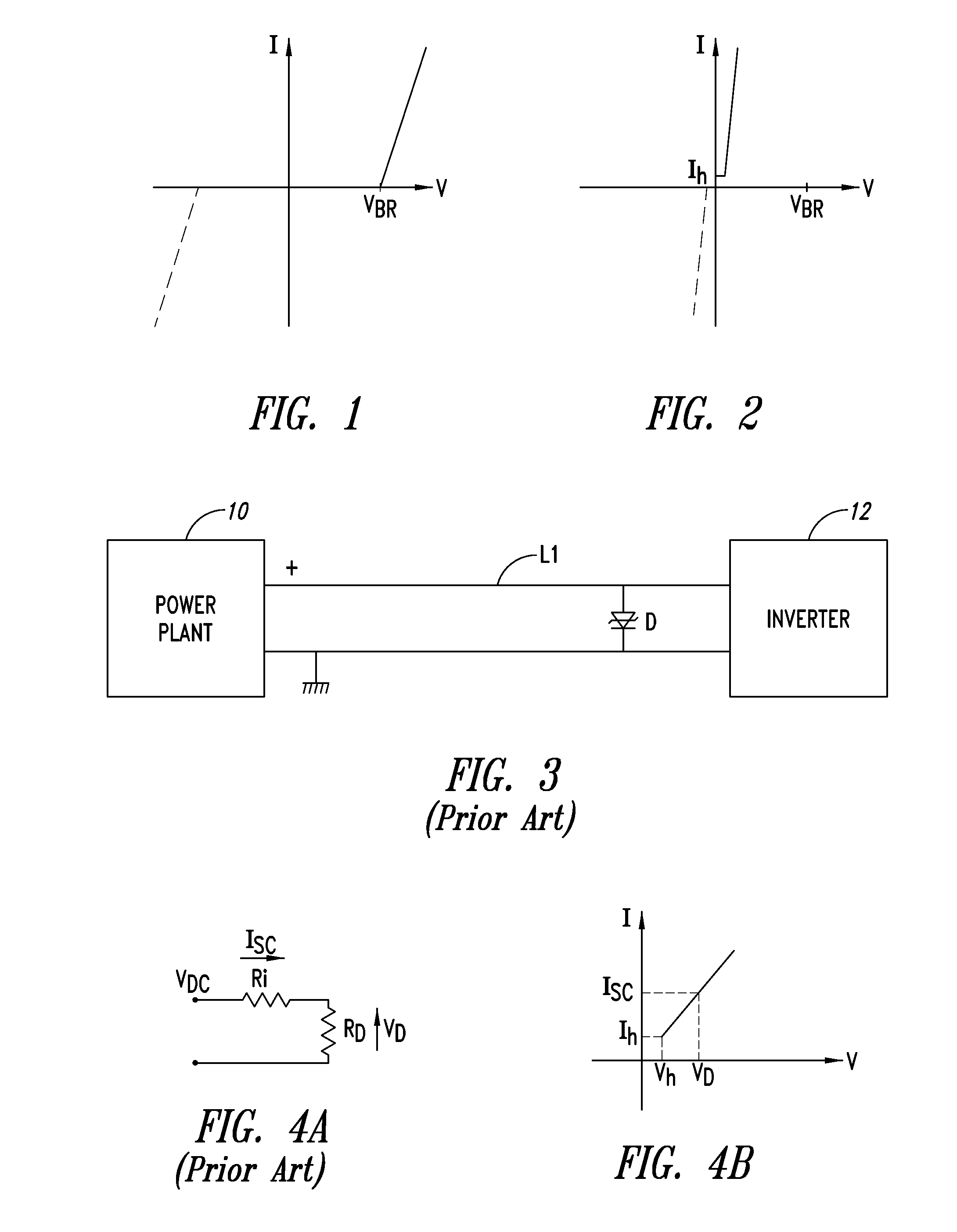
[0035]In the idle state, switch SW is off. Terminals A and B are connected across a D.C. power supply line so that the protection is for example connected like diode D of FIG. 3. As long as the voltage between terminals AB remains lower than the breakdown voltage of break-over diode D, the protection device is non-conductive. When an overvoltage appears, the protection diode becomes conductive, which results in the configuration of FIG. 4A, that is, the power supply connected between terminals AB is shorted. Once the overvoltage has passed, diode D conducts a short-circuit current IDC such as defined in relation with FIG. 4A. At this time, switch SW is turned on s...
PUM
 Abstract
Description
Claims
Application Information
 - R&D
- Intellectual Property
- Life Sciences
- Materials
- Tech Scout
- Unparalleled Data Quality
- Higher Quality Content
- 60% Fewer Hallucinations
Browse by: Latest US Patents, China's latest patents, Technical Efficacy Thesaurus, Application Domain, Technology Topic, Popular Technical Reports.
© 2025 PatSnap. All rights reserved.Legal|Privacy policy|Modern Slavery Act Transparency Statement|Sitemap|About US| Contact US: help@patsnap.com