
Short Gap Diverter

a diverter and short-gauge technology, applied in the direction of conveyor parts, mechanical conveyors, transportation and packaging, etc., can solve the problems of increasing the space requirements of the conveyor, limiting affecting the speed of the conveyor,

Inactive Publication Date: 2014-10-16
MACHINE SOLUTION PROVIDERS LLC
View PDF6 Cites 2 Cited by
  • Summary
  • Abstract
  • Description
  • Claims
  • Application Information

AI Technical Summary

Benefits of technology

This patent describes a diverter for a conveyor system that helps to direct and guide products as they move through the system. The diverter includes two fingers, one on the input conveyor and one on the primary delivery conveyor. These fingers are moveable and can be positioned to intersect with each other at a specific angle. The first finger is positioned to move through the intersection of the two planes and direct the product towards the secondary delivery conveyor. The second finger is positioned to move along the same plane as the first finger and guide the second product to the secondary delivery conveyor. The invention enables precise and accurate direction and guidance of products as they move through the conveyor system.

Problems solved by technology

The limiting factor for conveyor speed, in many such manufacturing processes, is at the packaging end where the fast moving product on a delivery conveyor must be stopped and stacked for packaging.
Where the speed of the delivery conveyor is very high and the moving product is stopped in a short distance, the product may be damaged during the packaging operation.
The provision of accelerating conveyors, however, increases the space requirements of the conveyors and increases the product speed that must be decelerated prior to packaging.
The time required to insert or remove a diversion element is short; however it significantly increases the gap required between two successive products.

Method used


Image

  • Short Gap Diverter
  • Short Gap Diverter
  • Short Gap Diverter

Examples


Embodiment Construction

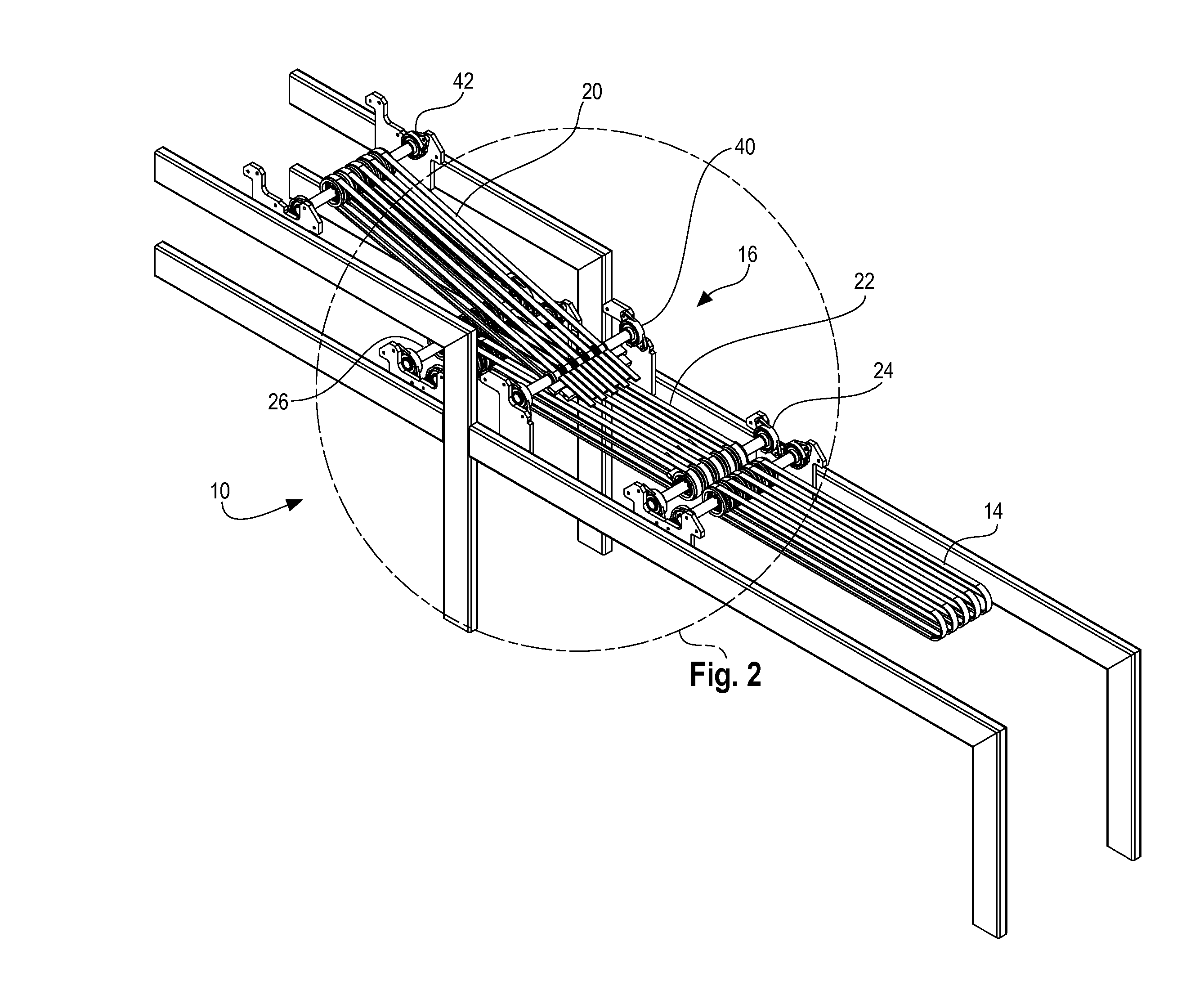
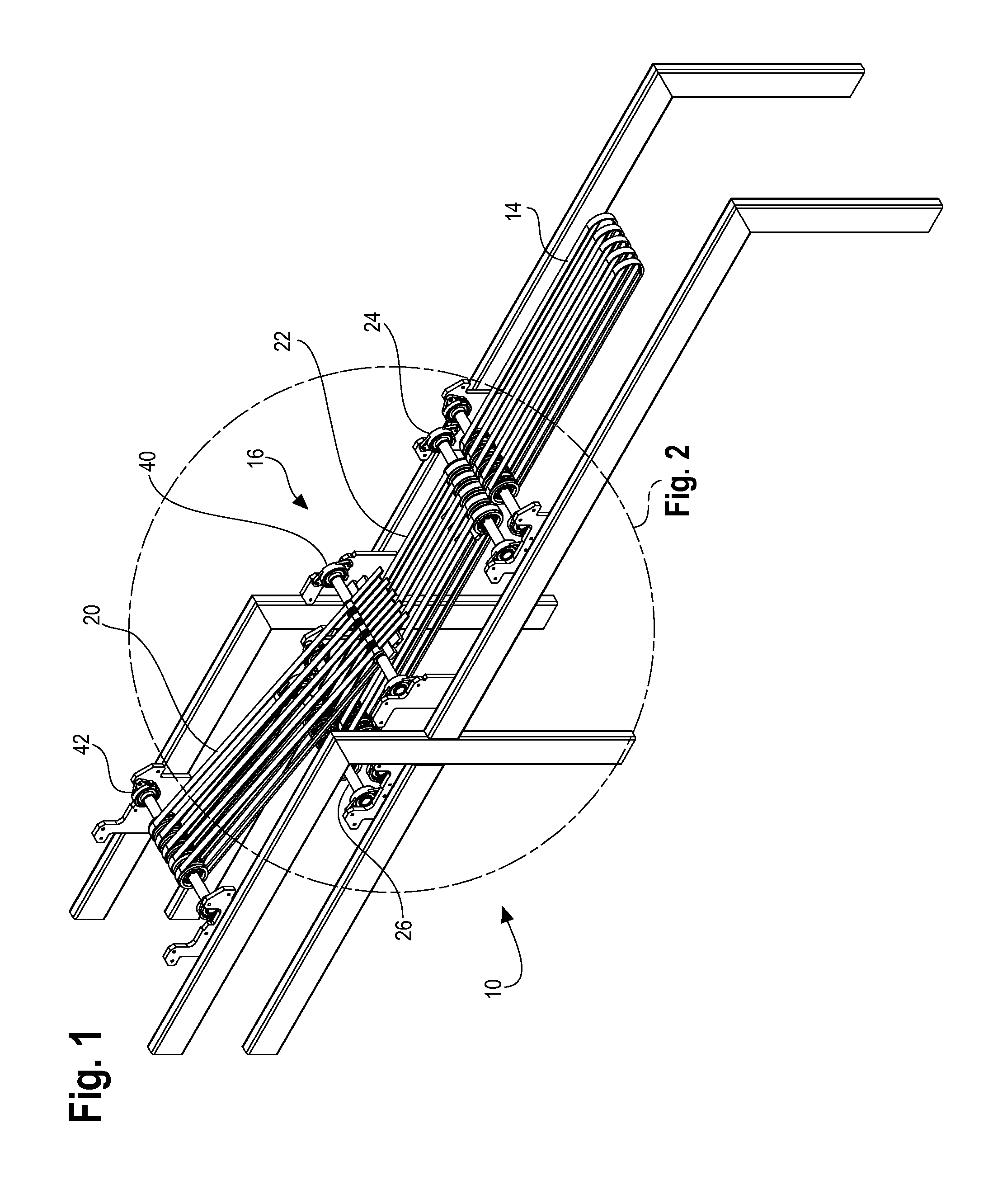
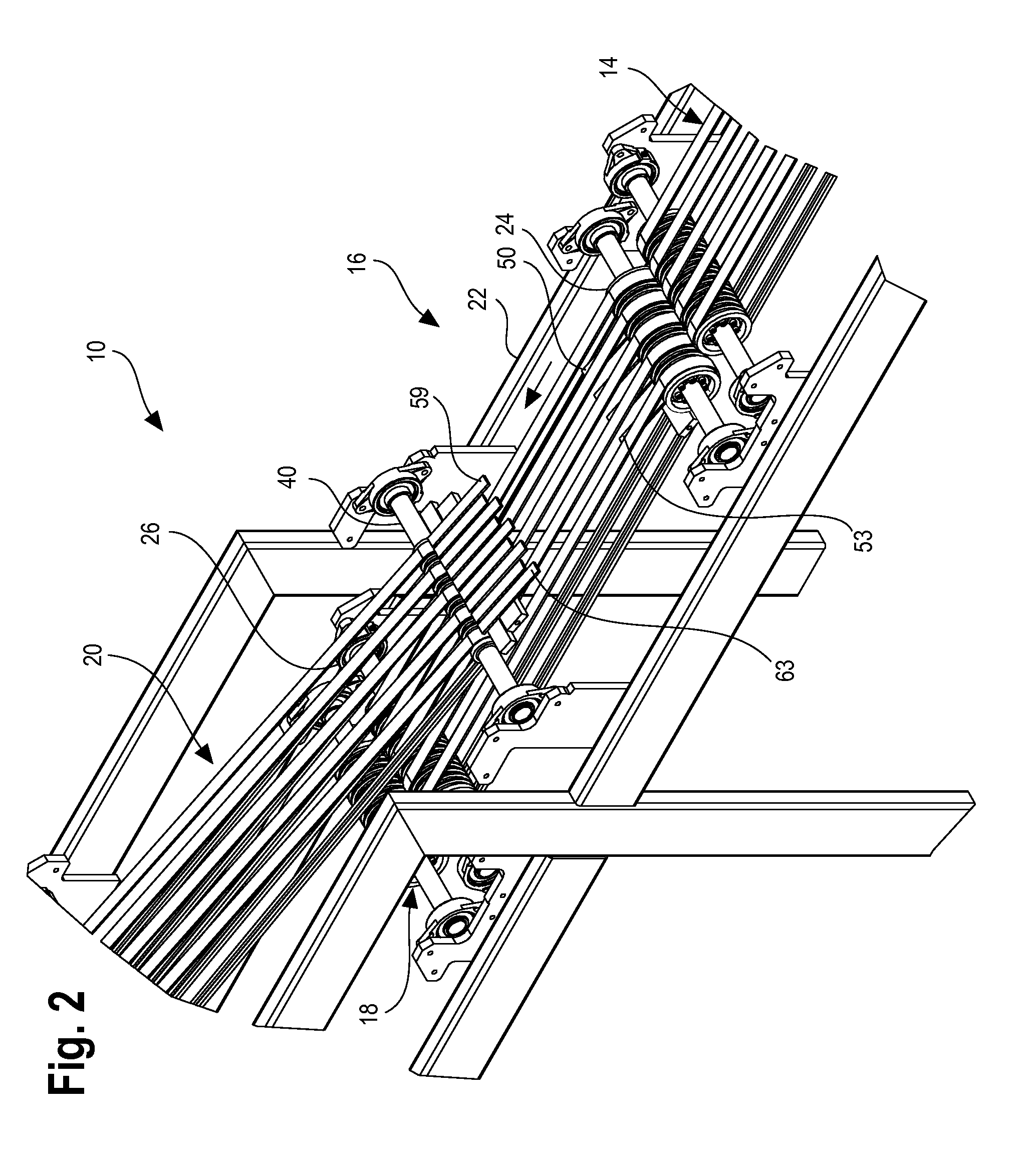
[0036]Referring to FIGS. 1 through 5, near the end of a manufacturing process for a generally planar product such as roofing shingles and the like, the substantially completed product moves along the upper surface of a conveyor to a cutter, not shown, that divides the elongate member into individual shingles or products 12. After the cutter, the products move to one or more packaging stations, not shown. To increase the speed at which the conveyor 10 operates, two packaging stations are provided. In order to accommodate two packaging stations, a speedup conveyor may be provided after the cutter to provide a gap between adjacent products 12. Regardless of the need for a speed up conveyor, following the cutter an input conveyor 14 carries the product 12 to a diverter 16, and following the diverter 16 is the primary delivery conveyer 18 that leads to the first packaging station. Positioned immediately above the primary delivery conveyor 18 is a secondary delivery conveyor 20, and betwe...


PUM


Abstract

A short gap diverter for a conveyor includes a plurality of spaced apart belts for transferring a product from a speed up conveyor to a primary delivery conveyor. A secondary delivery conveyor is positioned above the transit conveyor. A first set of fingers is positioned between the belts and is moveable from a position below the plane determined by the upper surfaces of the belts to a second position above the plane and angled toward the secondary delivery conveyor. A second set of fingers is mounted on the secondary delivery conveyor and moveable from a first retracted position to an extended position with the extended fingers forming a bridge for directing alternate products to the secondary delivery conveyor.

Description

[0001]Applicant Schreiber claims priority from his provisional application filed on Apr. 13, 2012 and assigned Ser. No. 61 / 623,983. The present application relates to assembly line diverters that divert every other product on a conveyer to a second conveyer wherein both the first and second conveyers feed packaging stations, and in particular to a short gap diverter that requires a minimum spacing between products to initiate a diversion.BACKGROUND OF THE INVENTION[0002]The manufacture of certain products, such as roof shingles, or other generally planar products, include a conveyor that moves the product, such as a length of material, through various manufacturing stages. In the case of manufacturing roofing shingles, a felt strip is treated and adhesive material and granulated particles are applied thereto. The elongate strip eventually passes through a cutter to cut the felt material into standard lengths after which a delivery conveyor transfers the cut shingles to a packaging s...

Claims


Application Information

Patent Timeline
Patent Type & Authority Applications(United States)
IPC IPC(8): B65G47/64
CPCB65G47/647B65G47/71
Inventor SCHREIBER, JOSEPH M.JORGENSEN, ARNE ROY
Owner MACHINE SOLUTION PROVIDERS LLC
Learn More