Mast-mounted aircraft generator

a generator and mast-mounted technology, applied in the field of systems and methods for generating electrical power onboard aircraft, can solve the problems of frequent maintenance and low efficiency of power generation devices

Inactive Publication Date: 2014-10-23
OECO
View PDF13 Cites 28 Cited by
  • Summary
  • Abstract
  • Description
  • Claims
  • Application Information

AI Technical Summary

Problems solved by technology

These power generation devices typically suffer from low efficiency and may require frequent maintenance.

Method used


Image

  • Mast-mounted aircraft generator
  • Mast-mounted aircraft generator
  • Mast-mounted aircraft generator

Examples


Embodiment Construction

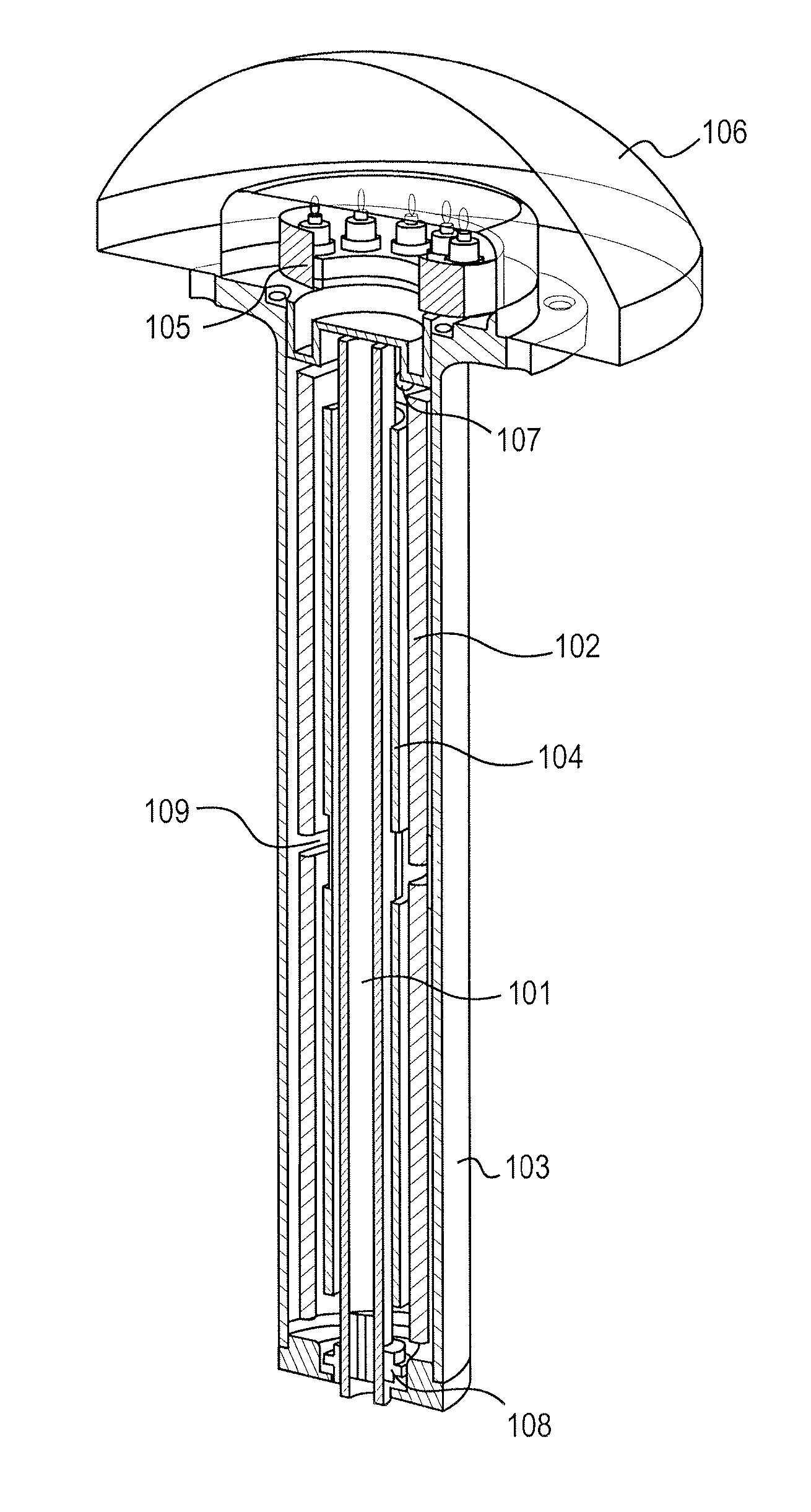
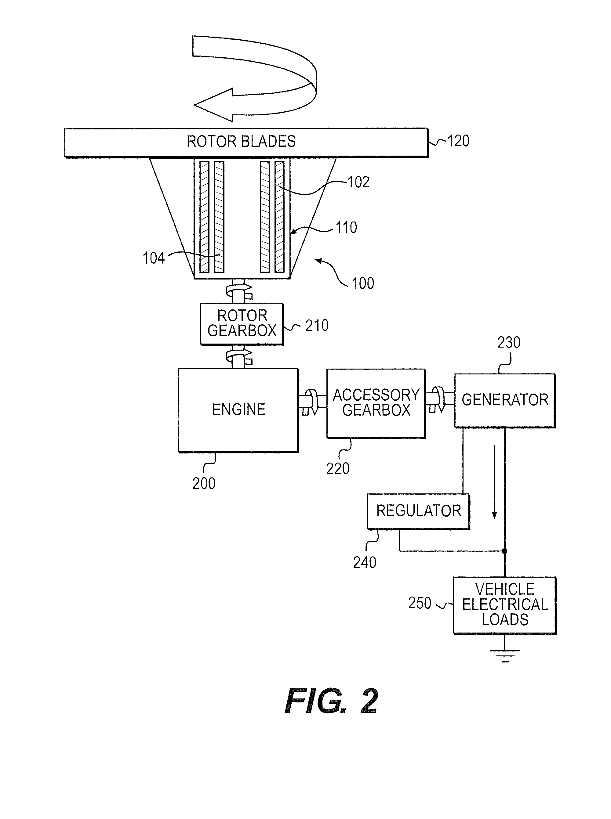
[0019]Reference will now be made in detail to embodiments of the present invention, examples of which are illustrated in the accompanying drawings. With reference to FIG. 2, in a first embodiment of the invention, a dedicated deicing generator 100 is mounted in or on the main mast 110 of a helicopter. The generator 100 may include an outer stator assembly 102 which serves as an armature and which is disposed about an inner rotor assembly 104 which serves as a field element. The electrical output of the generator 100 may be provided to resistive heating elements (not shown) associated with the rotor blades 120 without the use of slip rings by directly wiring the stator assembly 102 to the heating elements. The heating elements may prevent or melt the formation of ice on the rotor blades 120.

[0020]With continued reference to FIG. 2, the generator 100 may be operatively connected to a rotor gearbox 210 and a main engine 200. The main engine 200 may be operatively connected to an access...


PUM


Abstract

A generator with relatively high (Length / Diameter) aspect ratio, which may be mounted within the rotating mast of a helicopter, and which may generate power that is conditioned by a rotating power conditioning unit and delivered to the rotating rotor blades without the use of slip rings, is disclosed. The generator may be arranged to take advantage of the available space within the mast. Temperature of the mast and generator may be controlled by varying the wall thickness of the mast wall and using cooling fins on the mast and a cooling dome.

Description

CROSS REFERENCE TO RELATED APPLICATIONS[0001]This application relates to, and claims the benefit of the earlier filing date and priority of U.S. Provisional Patent Application No. 61 / 813,619, filed on Apr. 18, 2013, entitled “Mast-Mounted Generator With Counter-Rotating Stator.”FIELD OF THE INVENTION[0002]The present invention relates to systems and methods for generating electrical power onboard an aircraft, such as a helicopter.BACKGROUND[0003]Providing electrical power onboard a helicopter, particularly to helicopter rotor blades for deicing, has traditionally required the use of gearbox mounted generators, located remotely from the rotor blades, which transmit electrical power to the rotor blades through slip rings, as shown in FIG. 1. These power generation devices typically suffer from low efficiency and may require frequent maintenance. Accordingly, there is a need for an improved onboard generator for generating electrical power on an aircraft. In particular, there is a need...

Claims


Application Information

Patent Timeline
Patent Type & Authority Applications(United States)
IPC IPC(8): H02K7/14H02K11/00H02K5/18
CPCH02K7/14H02K11/0073H02K5/18B64D15/12H02K21/26H02K7/006H02K7/1807H02K11/042H02K16/00B64C27/12B64C27/32H02K5/04H02K2213/12H02K9/227
Inventor RAAD, BERNARD ANTHONY
Owner OECO
Why Eureka
Try Eureka