Footwear lacing system

a lacing system and shoe technology, applied in the field of lacing systems, can solve the problems of not providing a comfortable fit for everyone, and achieve the effect of better fitting the foot of a user

Inactive Publication Date: 2014-11-06
CHINOOK ASIA
View PDF9 Cites 19 Cited by
  • Summary
  • Abstract
  • Description
  • Claims
  • Application Information

AI Technical Summary

Benefits of technology

[0003]The subject invention provides a lacing system having lace-receiving elements, which are attachable to their res

Problems solved by technology

However, people's feet are unique, and even for a given shoe size any particular patt

Method used


Image

  • Footwear lacing system
  • Footwear lacing system
  • Footwear lacing system

Examples


Embodiment Construction

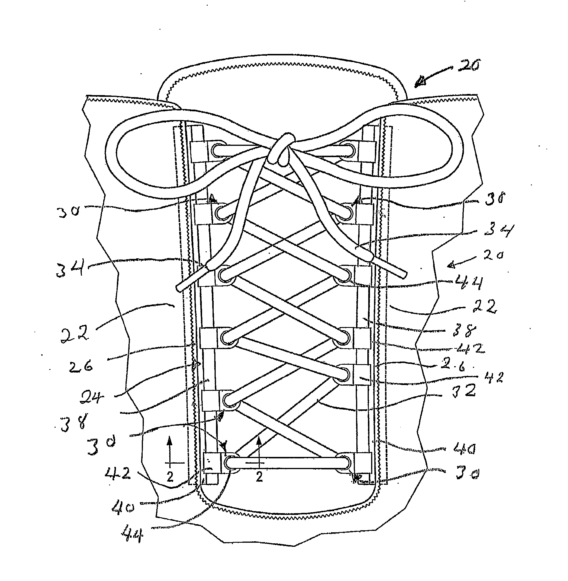
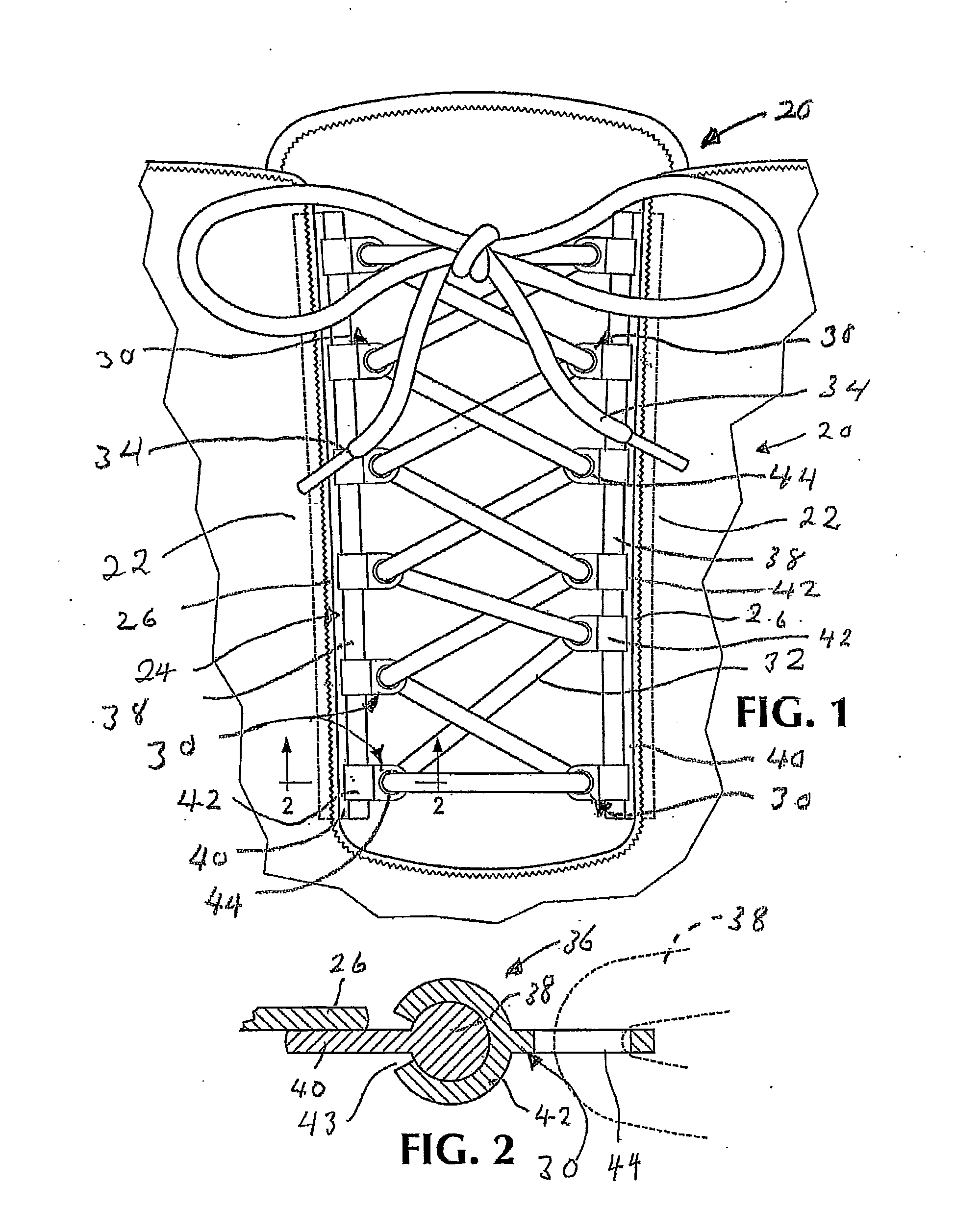
[0018]Referring now to FIGS. 1, 7 and 10 of the drawings, a boot 20, or other footwear, has a pair of opposed flaps 22, which are drawn together by a lacing system 24 to tighten the boot on a user's foot. The flaps have inwardly facing elongate margins 26. Attached to the margins 26 are a plurality of lace-receiving elements 30. A lace 32 extends between lace-receiving elements 30 on opposed flaps in a zigzag pattern such that when the extremities 34 of the lace are pulled, the lace acts through the lace-receiving elements 30 to draw the opposed flaps toward one another to tighten the boot on the user's foot. The lace-receiving elements 30 are attachable to the flaps 22 at multiple locations on the flaps. This allows the manner in which the flaps are drawn toward one another to be adjusted in order that the lacing system is tightened in a comfortable manner for a given user.

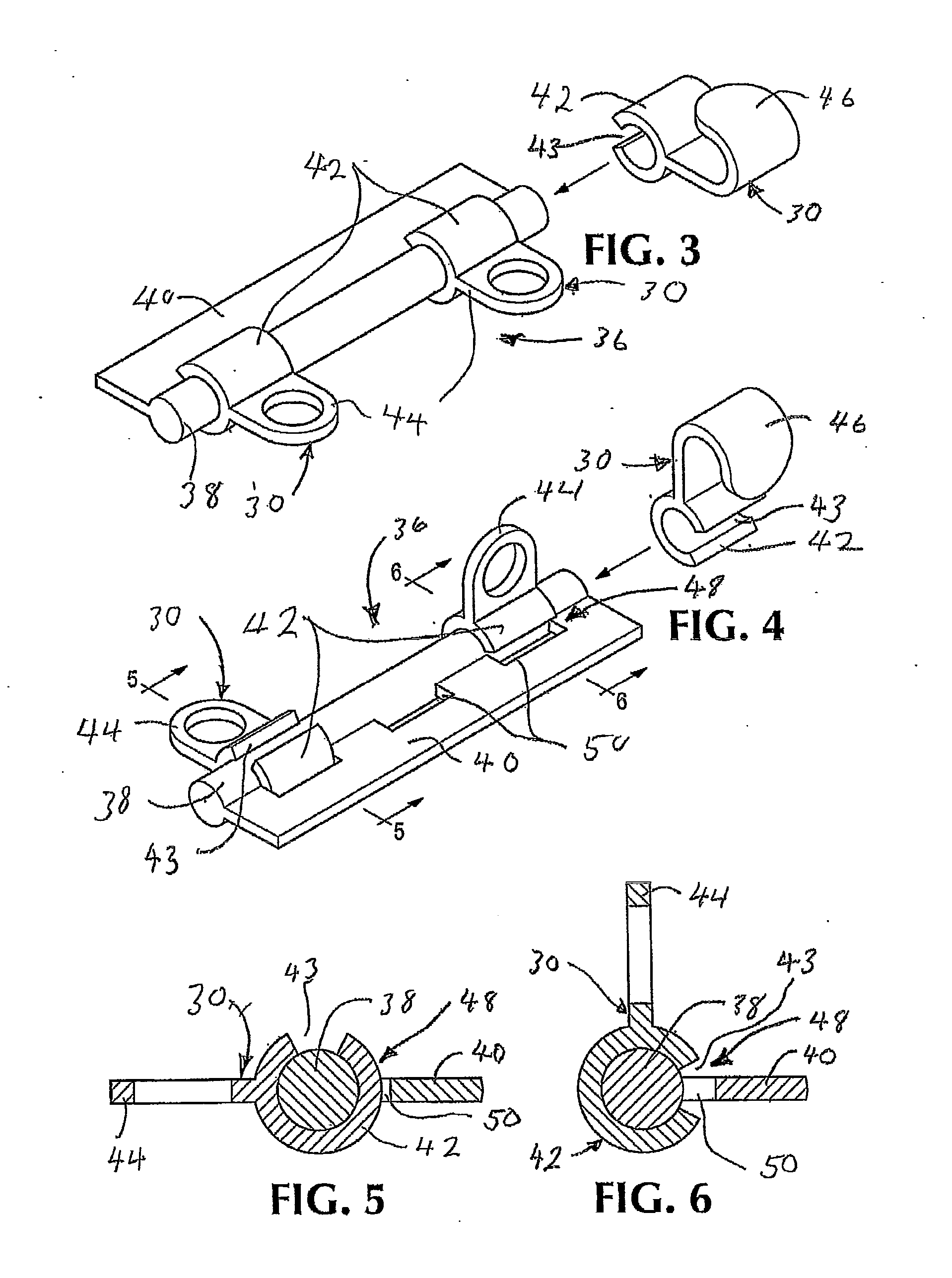
[0019]The lace-receiving elements 30 are attached to the flaps 22 by an attachment system 36. In a first embod...


PUM


Abstract

A lacing system for footwear of a type having a pair of spaced-apart flaps that are pulled together by tightening a lace includes a plurality of lace-receiving elements which are attachable to the flaps at multiple locations which allows the user to tailor the location of the lace-receiving elements to obtain a comfortable fit.

Description

CROSS-REFERENCE TO RELATED APPLICATIONS[0001]This is a Continuation-in-Part of application Ser. No. 13 / 839,245 filed Mar. 15, 2013.BACKGROUND OF THE INVENTION[0002]Boots and other footwear have opposed flaps which cover the tongue at the front of the boot. The ends of a lace, which is placed through eyes or around hooks in a zigzag pattern, are pulled to draw the flaps together and tighten the boot on the user's foot. However, people's feet are unique, and even for a given shoe size any particular pattern of the eyes or hooks on the flaps does not provide a comfortable fit for everyone.SUMMARY OF THE INVENTION[0003]The subject invention provides a lacing system having lace-receiving elements, which are attachable to their respective flaps at multiple locations, thereby allowing the lacing pattern to be varied to better fit the foot of a user.[0004]The foregoing and other objectives, features, and advantages of the invention will be more readily understood upon consideration of the f...

Claims


Application Information

Patent Timeline
IPC IPC(8): A43C11/00
CPCA43C11/004A43C1/003A43C1/04A43C3/00A43C11/12
Inventor LINTH, ANDREW J.
Owner CHINOOK ASIA
Why Eureka
Try Eureka