Methods and apparatus to prevent movement through artificial disc replacements

a technology of artificial discs and methods, applied in the field of surgical methods and equipment, can solve the problems of preventing successful fusion, affecting the function of the disc, and insufficient anterior spinal fusion, so as to facilitate spinal fusion and improve the fit

Inactive Publication Date: 2006-03-09
FERREE BRET A
View PDF79 Cites 153 Cited by
  • Summary
  • Abstract
  • Description
  • Claims
  • Application Information

AI Technical Summary

Benefits of technology

[0014] This invention is directed to improved methods and devices to attach arthroplasty devices, particularly the spine, distract the disc space, machine the disc space to improve the fit between ADRs and the vertebrae, to hold and remove ADRs, and to facilitate spinal fusion for a failed ADR surgery.

Problems solved by technology

Many surgeons believe a posterior spinal fusion is inadequate following ADR insertion.
They believe continued movement through the ADR will prevent a successful fusion.
All surgeons agree that removal of ADRs, particularly in the lumbar spine, is dangerous procedure.
The fragile vessels may be torn during revision surgery.
Tears of the great vessels may be life threatening.
The nucleus becomes thinner and less able to handle compression loads.
The redundant annular fibers are less effective in controlling vertebral motion.
The prior-art technique subjects the anchoring devices to excessive forces.
Excessive forces on the anchoring devices frequently cause movement between the vertebrae and the anchoring components.

Method used


Image

  • Methods and apparatus to prevent movement through artificial disc replacements
  • Methods and apparatus to prevent movement through artificial disc replacements
  • Methods and apparatus to prevent movement through artificial disc replacements

Examples


Embodiment Construction

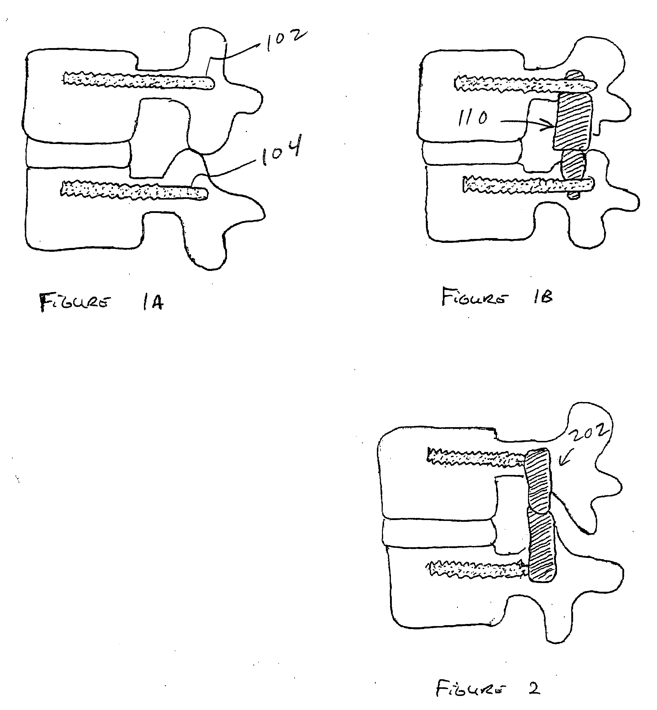
[0133]FIG. 1A is a sagittal cross section of the spine and screws 102, 104 used to anchor a spinal arthroplasty device (not shown). The screws are partially contained in the pedicles of the vertebrae. The screws, or other anchoring devices, could be placed in other areas of the vertebrae. FIG. 1B is a sagittal cross section of the spine and a dynamic stabilization device 110. A suitable device is taught in my co-pending U.S. patent application Ser. No. 10 / 412,896, the entire content of which is incorporated herein by reference. The dynamic stabilization device may be connected to the pedicle screws during a second operation several months after inserting screws 102,104.

[0134]FIG. 2 is a sagittal cross section of the spine, anchoring components, and a facet replacement device 202 attached to the anchoring components during a second procedure after inserting the anchoring components.

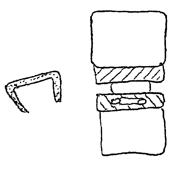
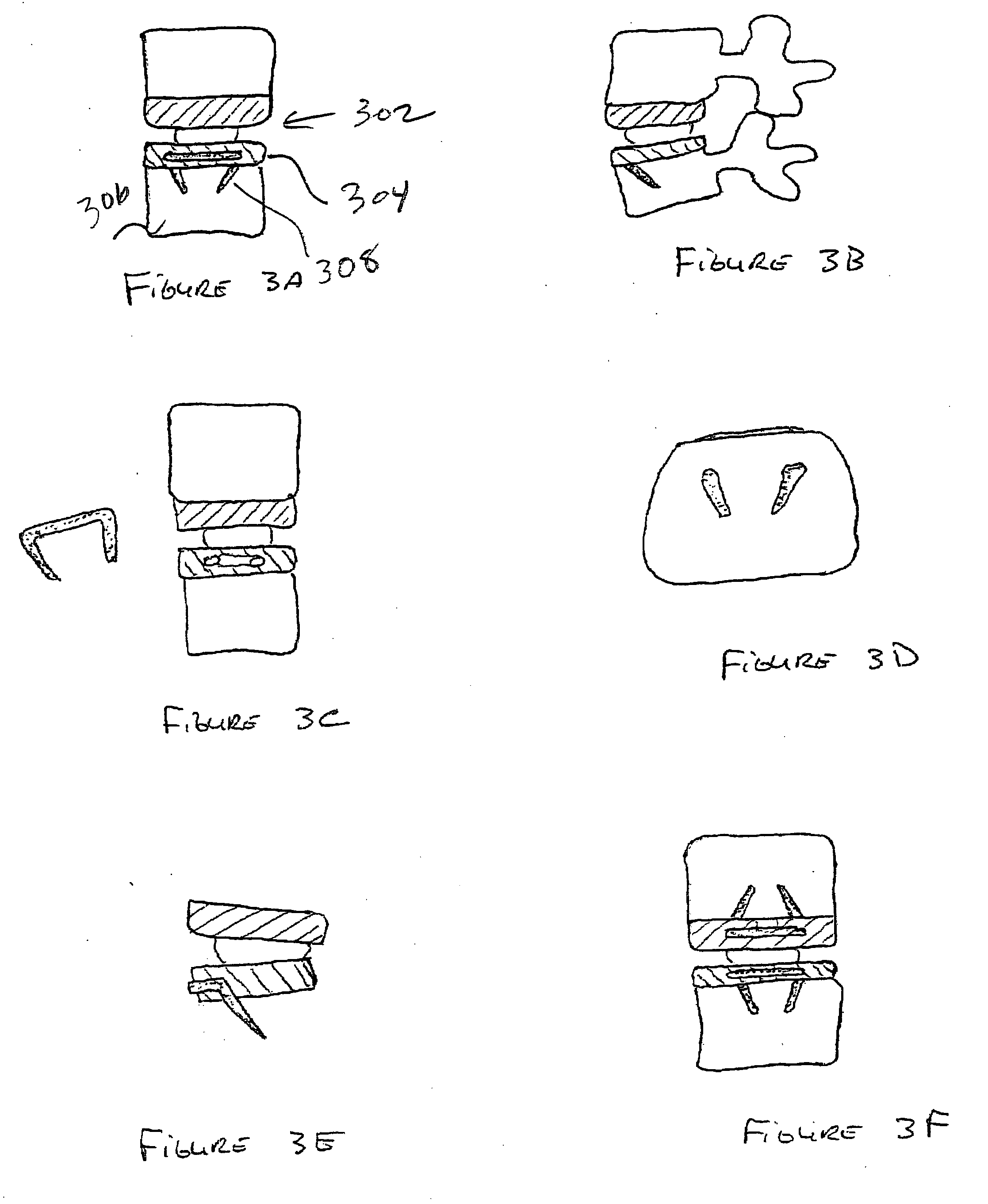
[0135]FIG. 3A is a coronal cross section of the spine and an artificial disc replacement (ADR) 302. T...


PUM


Abstract

This invention is directed to improved methods and devices to attach arthroplasty devices, particularly the spine, distract the disc space, machine the disc space to improve the fit between ADRs and the vertebrae, to hold and remove ADRs, and to facilitate spinal fusion for a failed ADR surgery. One aspect of the invention places anchor devices in the spine during a first operation. Spinal devices are connected to the anchoring devices during a second procedure. The second procedure is generally performed months after the insertion of the anchoring devices. The time between the two procedures allows bone to grow into the anchoring devices. Minimal forces are exerted on the anchoring devices between the procedures. Other embodiments are described where a previously implanted ADR having a pair of opposing endplates is immobilized using a device the attached to the endplates, fits between the endplates, or both.

Description

REFERENCE TO RELATED APPLICATIONS [0001] This application claims priority from U.S. Provisional Patent Application Ser. No. 60 / 608,401, filed Sep. 9, 2004, the entire content of which is incorporated herein by reference.FIELD OF THE INVENTION [0002] This invention relates generally to surgical methods and apparatus and in particular to methods and apparatus for preventing movement through artificial disc replacements. BACKGROUND OF THE INVENTION [0003] A small percent of patients will continue to experience low back pain (LBP) following insertion of Artificial Disc Replacements (ADR). Surgeons often fuse the vertebrae immediately above and below the ADR in an attempt to decrease patients' LBP. Patients' spine may be fused from a posterior approach to the spine. Pedicle screws and other types of spinal instrumentation may be used to facilitate fusion. Many surgeons believe a posterior spinal fusion is inadequate following ADR insertion. They believe continued movement through the ADR...

Claims


Application Information

Patent Timeline
Patent Type & Authority Applications(United States)
IPC IPC(8): A61F2/44A61B17/70
CPCA61B17/025A61F2250/0097A61B17/15A61B2017/0256A61B2017/0641A61B2017/0648A61F2/4425A61F2/4611A61F2002/30092A61F2002/30093A61F2002/30112A61F2002/30331A61F2002/30367A61F2002/30383A61F2002/30387A61F2002/30405A61F2002/30433A61F2002/30448A61F2002/30471A61F2002/30481A61F2002/30484A61F2002/30515A61F2002/30517A61F2002/30578A61F2002/30617A61F2002/443A61F2002/449A61F2002/4619A61F2002/4622A61F2002/4627A61F2002/4628A61F2210/0014A61F2210/0019A61F2220/0025A61F2220/0033A61F2220/0041A61F2220/005A61F2220/0091A61F2230/0004A61B17/0642
Inventor FERREE, BRET A.
Owner FERREE BRET A
Why Eureka
Try Eureka