Anterior lumbar fusion method and device

a lumbar fusion and anterior lumbar fusion technology, applied in the field of anterior lumbar fusion methods and devices, can solve the problems of limited size and shape of implants, failure of implants, weakening of vertebrae, etc., and achieves the effect of reducing the contact surface area, and reducing the risk of fractur

Active Publication Date: 2017-07-18
NUTECH SPINE
View PDF54 Cites 0 Cited by
  • Summary
  • Abstract
  • Description
  • Claims
  • Application Information

AI Technical Summary

Benefits of technology

[0007]In one embodiment, the present invention relates to methods and devices for placing spinal implants. The implants are sized so as to be inserted between vertebral bodies in at least pairs. The interbody implants are placed completely within the space previously occupied by the intervertebral disc and are supported between the cortical bone surfaces of the adjacent vertebrae. The method does not require drilling or boring into the vertebral bone. The height of the implants is larger in the middle than at the ends providing for a convex shape. The convex shape allows the bottom portion of the implant to contact the vertebral body. This maximizes the contact surface area between the implant and the adjacent vertebral bodies and provides improved support to the adjacent vertebrae and thus inhibited movement of the implant after insertion. An insertion instrument places the implant in at least pairs with a variable-sized space placed in between. The spinal implants are used to facilitate spinal fusion, correct deformities, stabilize and strengthen the spine. The implants are made of a biocompatible material and are particularly suited for anterior lumbar interbody fusion surgery.

Problems solved by technology

However, the size and shape of the implant is limited by the natural contours of the spine and the vertebral body.
These procedures may weaken the vertebral structure and may contribute to failure of the implant.
Therefore, one challenge encountered in spinal implant surgical procedures is manufacturing an implant that replicates the general dimensions of the intervertebral disk.

Method used


Image

  • Anterior lumbar fusion method and device
  • Anterior lumbar fusion method and device
  • Anterior lumbar fusion method and device

Examples


Embodiment Construction

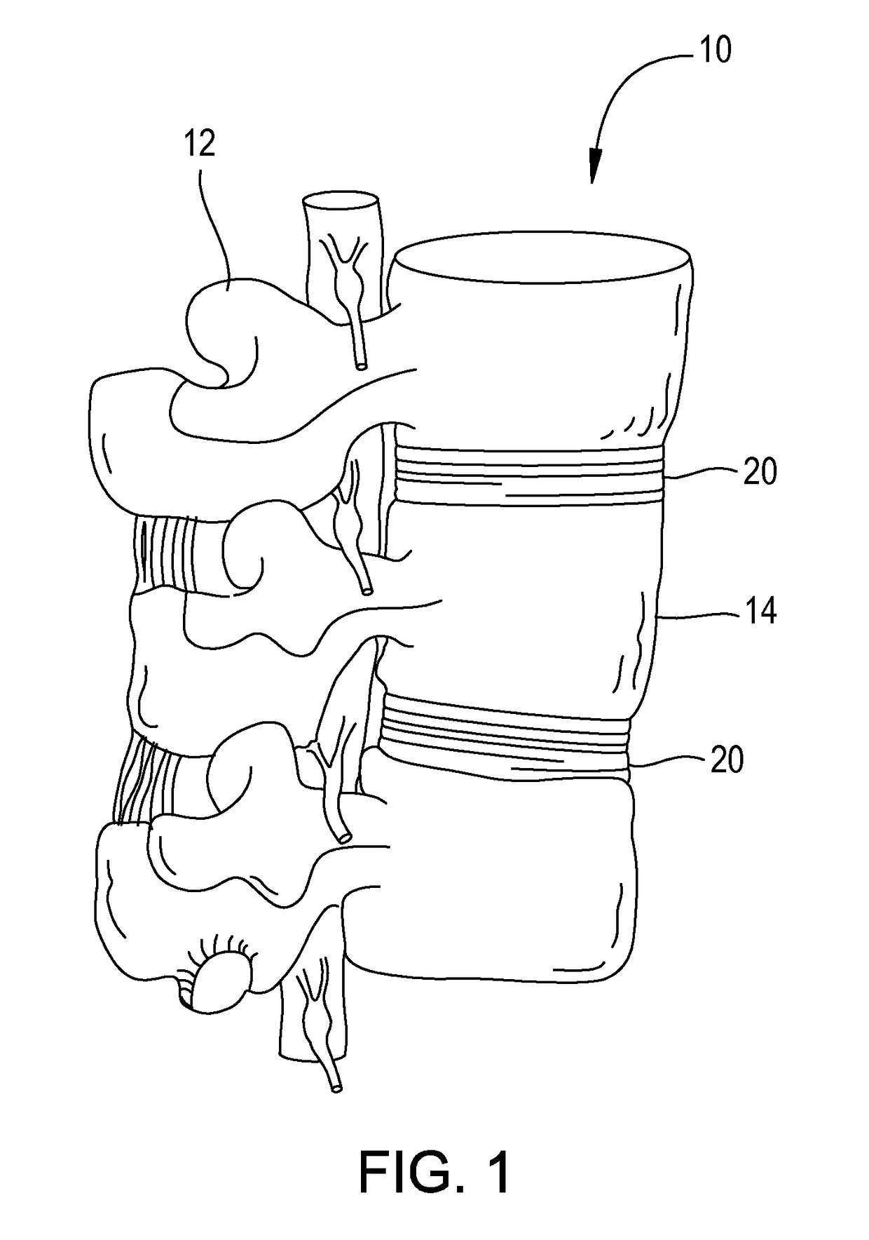
[0033]As FIG. 1 shows, the spinal column 10 includes a number of uniquely shaped bones, called the vertebrae 12. The number of vertebrae 12 that make up the spinal column 10 depends upon the species of animal. In a human there are twenty-four vertebrae 12, including seven cervical vertebrae, twelve thoracic vertebrae and five lumbar vertebrae.

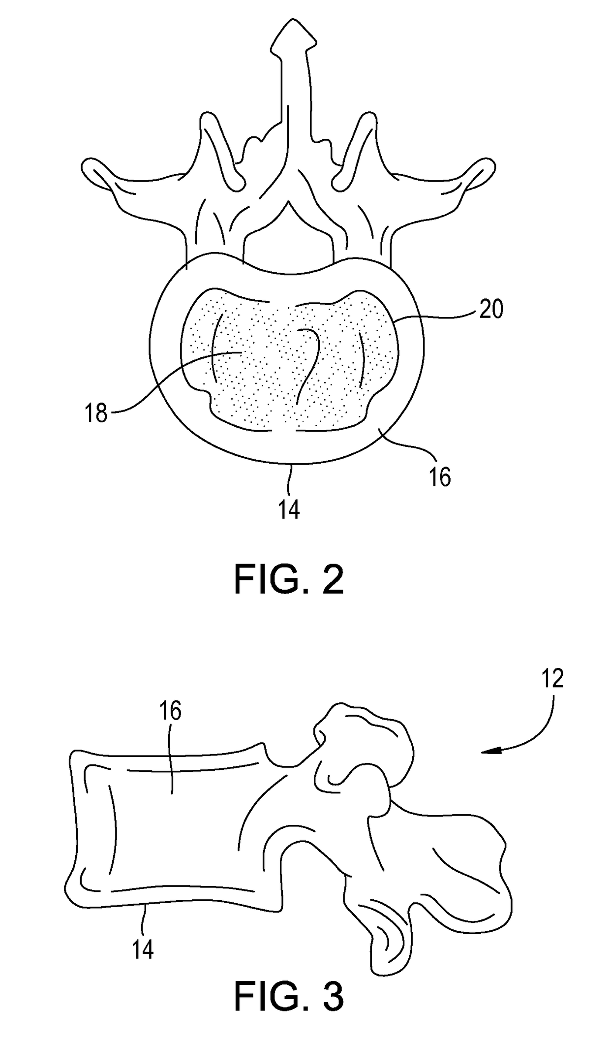
[0034]As FIGS. 1 to 3 show, each vertebra 12 includes a vertebral body 14, which extends on the anterior (i.e., front or chest) side of the vertebra 12. As FIGS. 1 to 3 show, the vertebral body 14 is in the shape of an oval disk. Referring to FIG. 2, the vertebral body 12 includes an exterior formed from compact cortical bone 16. The cortical bone 16 encloses an interior volume of reticulated cancellous, or spongy, bone 18 (also called medullary bone or trabecular bone) and is raised to form a lip that encircles the cancellous bone. A “cushion,” called an intervertebral disk 20, is located between vertebral bodies 14.

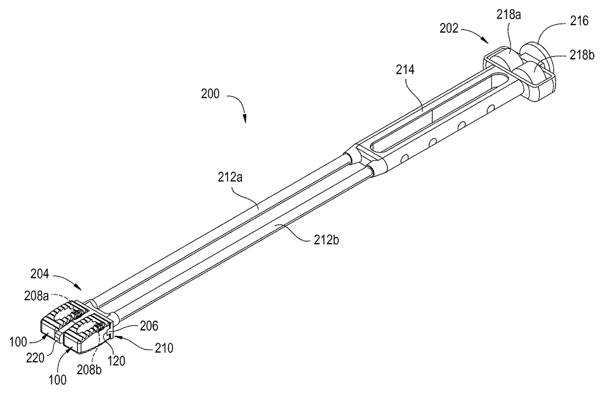
[0035]FIGS. 4 to 10 illustr...


PUM


Abstract

A method and devices for placing spinal implants including placing the implants completely within a spaced defined between adjacent vertebral bodies where the implants are supported by the cortical bone of the vertebral bodies. An insertion instrument places the implants in pairs with a variable-sized space placed in between. The implants are made of a biocompatible material and are particularly suited for anterior lumbar interbody fusion surgery. The spinal implants used to facilitate spinal fusion, correct deformities, stabilize and strengthen the spine.

Description

RELATED APPLICATIONS[0001]This application claims priority to U.S. Provisional Patent Application No. 61 / 793,616, filed on Mar. 15, 2013 and titled, “Anterior Lumbar Fusion Method and Device,” the entire contents of which are incorporated herein by reference.FIELD OF THE INVENTION[0002]The present invention relates to methods and devices for placing spinal implants. More particularly, the invention is directed to spinal implants used to facilitate spinal fusion and correct deformities and stabilize and strengthen the spine. The implants are inserted in pairs with a variable-sized space placed in between. The implants are made of a biocompatible material and are particularly suited for anterior lumbar interbody fusion surgery.BACKGROUND OF THE INVENTION[0003]Anterior lumbar interbody fusion (ALIF) is a surgical procedure used to join two or more vertebrae. Interbody fusion includes removing an intervertebral disc and replacing the disc with an implant. The implant may be naturally oc...

Claims


Application Information

Patent Timeline
Patent Type & Authority Patents(United States)
IPC IPC(8): A61F2/44A61F2/46A61F2/30
CPCA61F2/4611A61F2/447A61F2/4684A61F2002/3055A61F2002/3082A61F2002/30904A61F2002/448A61F2002/4475A61F2002/4627A61F2002/4629A61F2002/30593
Inventor SCHIFFMAN, JEFFREY S.EASTLACK, ROBERT K.MALY, RICHARD S.WALTHALL, JR., HOWARD P.
Owner NUTECH SPINE
Why Eureka
Try Eureka