Multi-tilt micromirror systems with concealed hinge structures

Inactive Publication Date: 2005-05-31
SK HYNIX INC
View PDF43 Cites 90 Cited by
  • Summary
  • Abstract
  • Description
  • Claims
  • Application Information

AI Technical Summary

Benefits of technology

[0015]The approach to mirror and hinge support or attachment described helps maximize available reflective surface area, Utilizing side-support features according to the present invention enables production of certain mirror face embodiments that are unbroken by light-scattering or non-reflective features. This approach and other useful design characteristics are described much more extensively in co-pending, commonly owned applications Ser. Nos. 10/269,796; 10/269,763 and 10/269,478, each filed Oct. 11, 2002 and each incorporated by reference herein in its entirety. Particularly, in connection with a sid

Problems solved by technology

These types of arrays are less suitable for reflecting larger, continuous light such as an optical image.
Generally, the support structures between actuating mirror elements leave too much space and thus create noticeable holes in the reflected image.
Many current designs may only move in one axis, which limits some of their potential applications.
Others that can move in a multi-axis fashion also often have relatively large gaps from one

Method used


Image

  • Multi-tilt micromirror systems with concealed hinge structures
  • Multi-tilt micromirror systems with concealed hinge structures
  • Multi-tilt micromirror systems with concealed hinge structures

Examples


Embodiment Construction

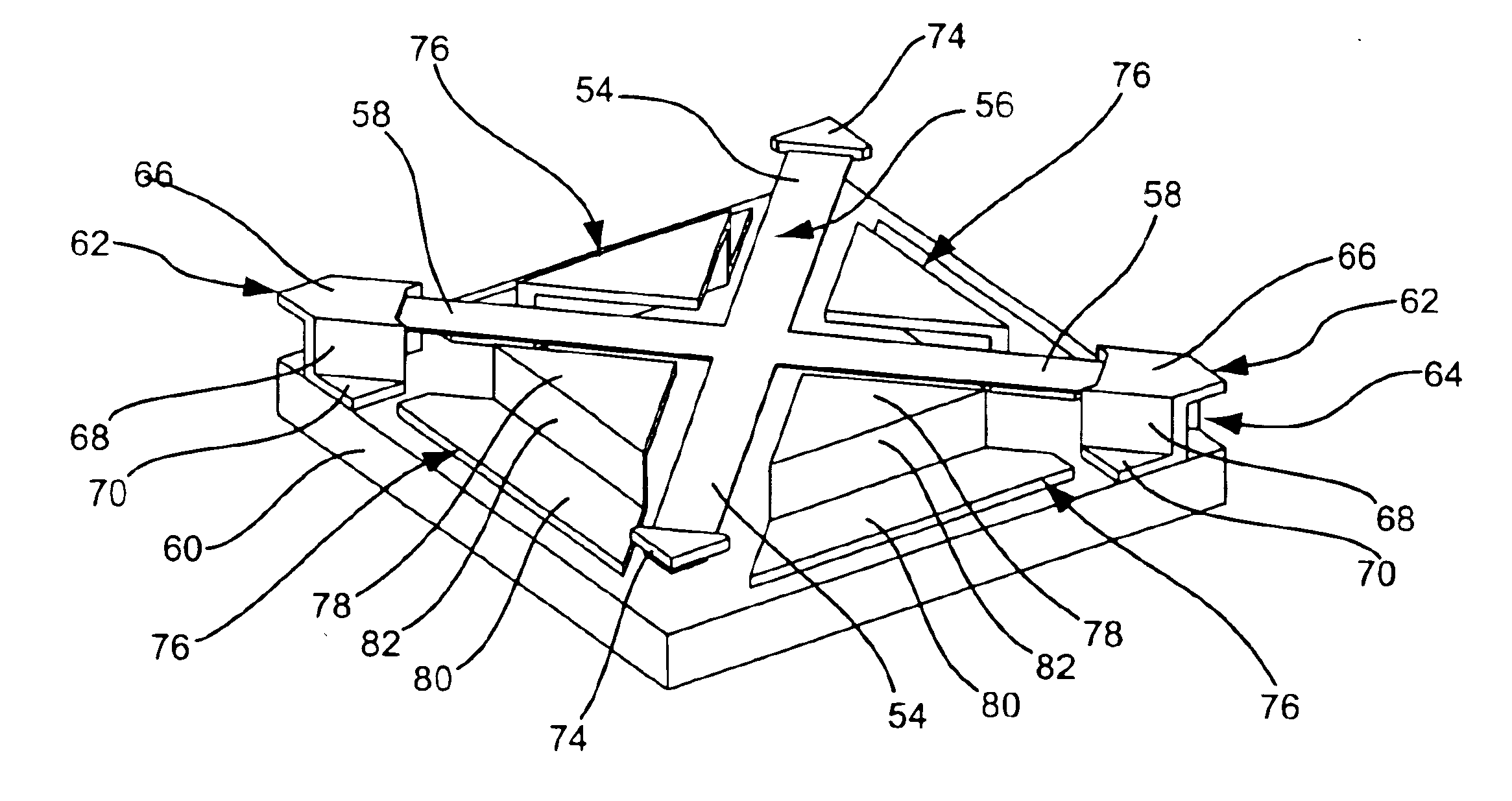
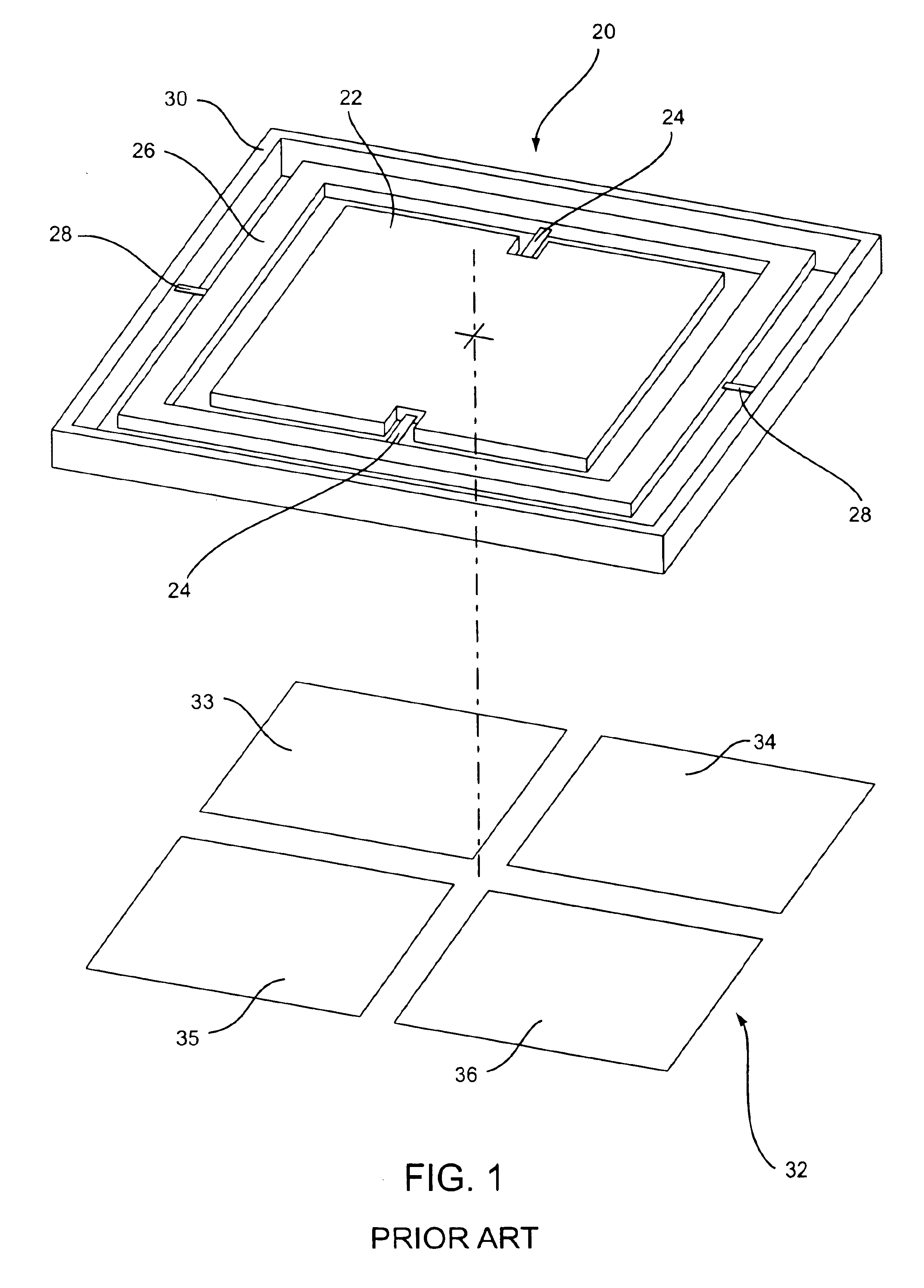
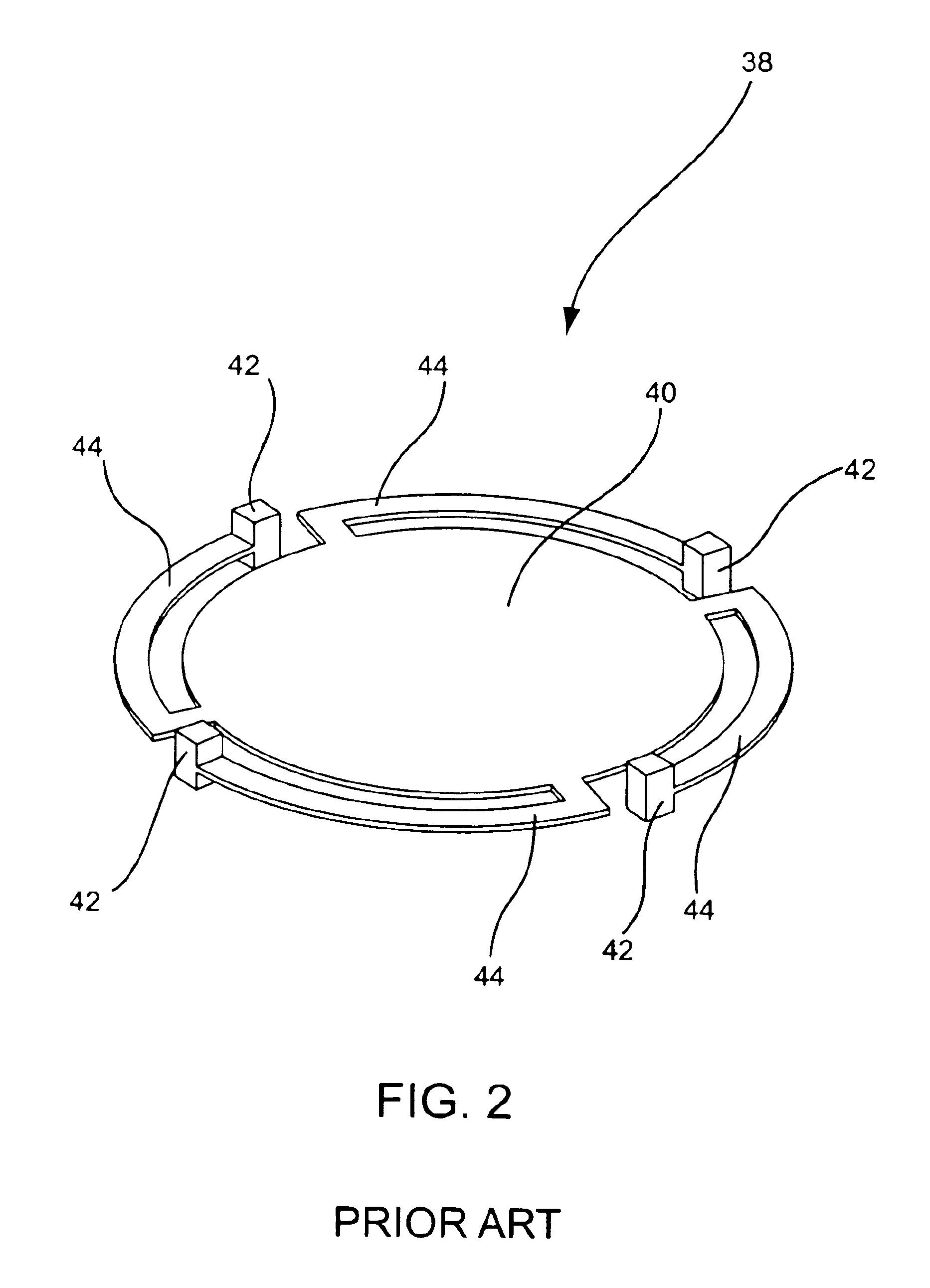
[0034]In describing the invention in greater detail than provided in the Summary above, applicable technology is first described. Following this is a detailed description of exemplary micromirror devices and assemblies according to the present invention, as well as an exemplary process of production. Application of the invention as a programmable lens surface is also discussed. This discussion is followed by description of a known optical switching matrix and its function. Finally, the applicability of the micromirrors of the present invention to optical switch technology, as well as to other fields of adaptive optics is discussed.

[0035]Before the present invention is described in such detail, however, it is to be understood that this invention is not limited to particular variations set forth, as such may, of course, vary. Various changes may be made to the invention described and equivalents may be substituted without departing from the true spirit and scope of the invention. It i...


PUM


Abstract

Multi-tilt mirrors, assemblies and applications of the same, and methods of making. Micromirror devices employing a superstructure that includes a mirror supported over a hinge set above substructure. Various features described are applicable to improve manufacturability, enable further miniaturization of the elements and/or to increase relative light return. Devices can be produced utilizing the various optional features described herein to provide miniaturized, highly controllable optics solutions.

Description

FIELD OF THE INVENTION[0001]The present invention relates generally to the field of spatial light modulators that can modify or correct an optical wavefront. More particularly, the invention relates to micro electro-mechanical systems (MEMS) in the form of micromirror devices used in adaptive optics, optical switching applications, or other light manipulation applications such as displays.BACKGROUND OF THE INVENTION[0002]MEMS devices are small structures, typically fabricated on a semiconductor wafer using processing techniques including optical lithography, metal sputtering or chemical vapor deposition, and plasma etching or other etching techniques that have been developed for the fabrication of integrated circuits. Micromirror devices are a type of MEMS device. Other types of MEMS devices include accelerometers, pressure and flow sensors, fuel injectors, inkjet ports, and gears and motors, to name a few. Micromirror devices have already met with a great amount of commercial succe...

Claims


Application Information

Patent Timeline
IPC IPC(8): G02B26/08
CPCG02B26/0841G02B26/0866G02B26/0858G02B26/085
Inventor AUBUCHON, CHRISTOPHER M.
Owner SK HYNIX INC
Why Eureka
Try Eureka