
Micromirror systems with side-supported mirrors and concealed flexure members

a technology of mirrors and micromirrors, applied in the field of spatial light modulators, can solve the problems of low contrast ratio, unsuitable for most image display applications, and very dim schlieren systems, and achieve the effect of maximizing the available reflective surface area

Inactive Publication Date: 2005-03-22
EXAJOULE
View PDF44 Cites 37 Cited by
  • Summary
  • Abstract
  • Description
  • Claims
  • Application Information

AI Technical Summary

Benefits of technology

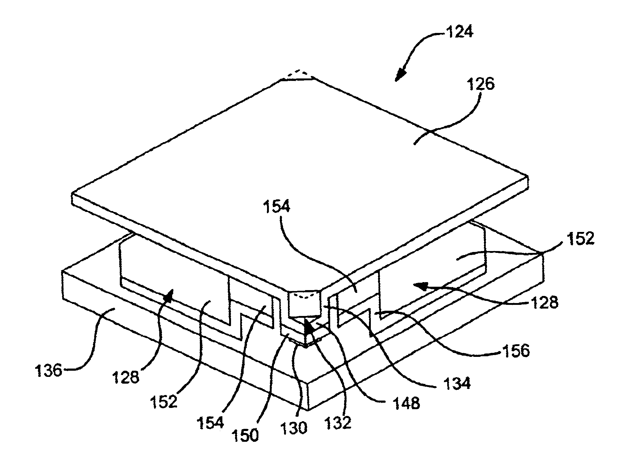
The approach to mirror and hinge support or attachment described helps maximize available reflective surface area. Utilizing side-support features according to the present invention enables production of certain mirror face embodiments that are unbroken by light-scattering or non-reflective features. In connection with such a mirror support approach, manufacturing techniques are taught in which support precursor regions that are ultimately removed are temporarily located where space is to be opened upon releasing the individual micromirror elements of an array. As such, the space required for effectively depositing / forming support structures is not wasted but falls within space that must be left open anyway in order to allow mirror actuation. In other variations of the invention, more traditional columnar mirror supports formed within “vias” are provided. However, these are still located at opposite sides of a given mirror.

Problems solved by technology

The images formed by Schlieren systems were very dim and had low contrast ratios, making them unsuitable for most image display applications.
Though improved, the support structure of these devices was in the optical path, and therefore contributed to an unacceptable amount of scattered light.
Yet another performance aspect in which improvement is possible concerns power consumption.

Method used


Image

  • Micromirror systems with side-supported mirrors and concealed flexure members
  • Micromirror systems with side-supported mirrors and concealed flexure members
  • Micromirror systems with side-supported mirrors and concealed flexure members

Examples


Embodiment Construction

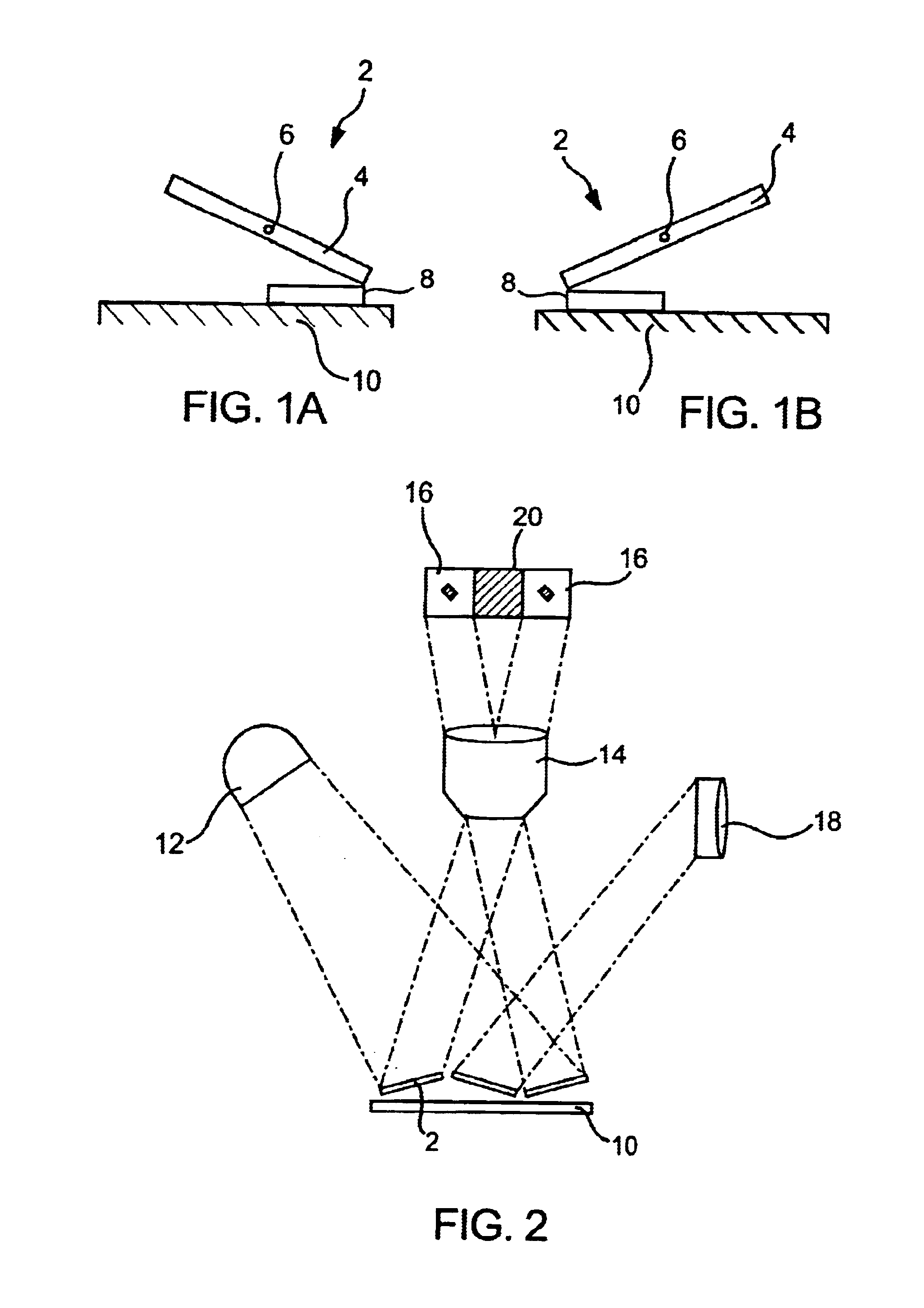
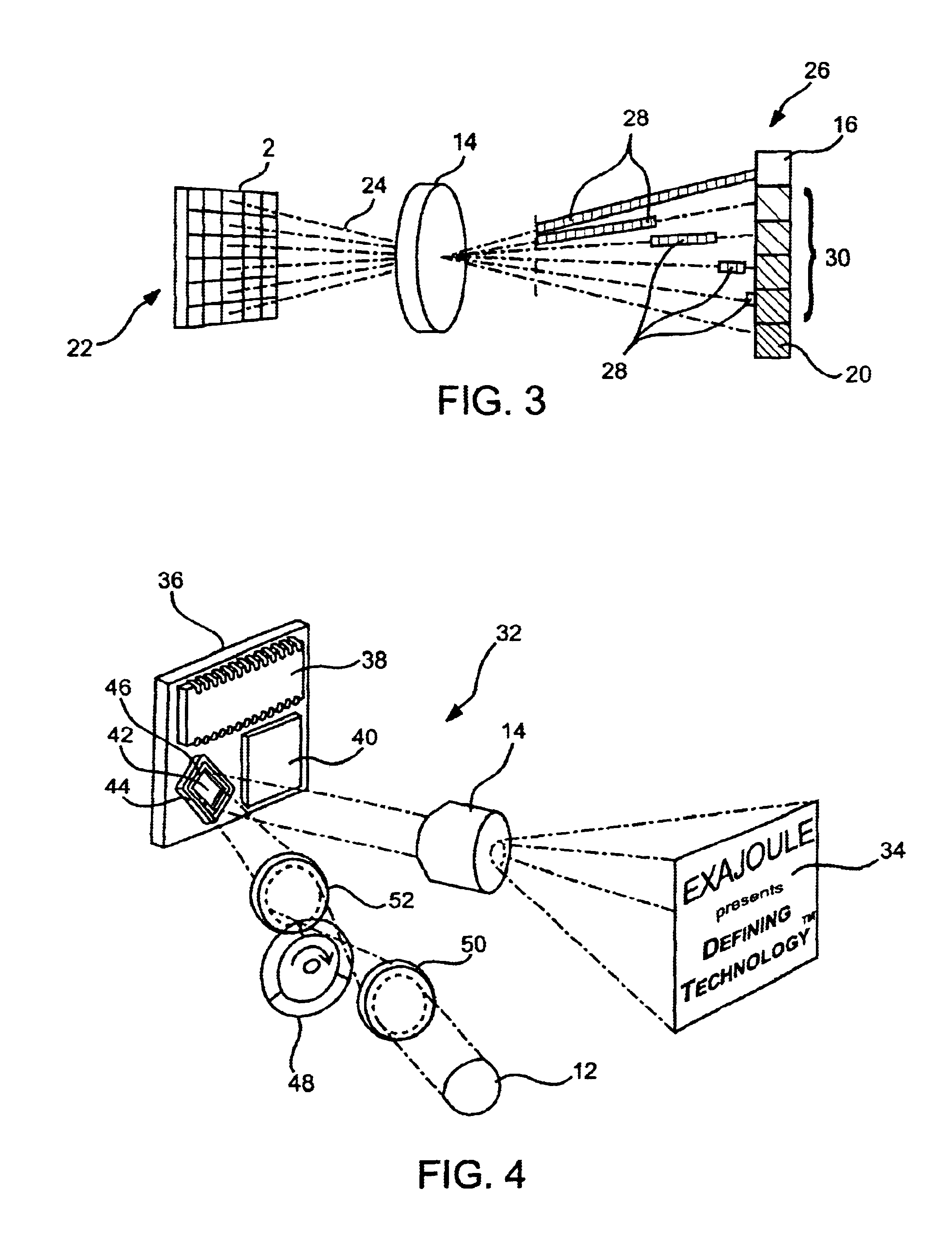
In describing the invention in greater detail than provided in the Summary above, applicable technology is first described. This discussion is followed by description of a known micromirror device and its manner of production. Then a variation of a micromirror device according to the present invention is disclosed, as well as a preferred manner of production. Next, comparative views of the known and inventive micromirror devices are described. Finally, additional optional aspects of the present invention are described, including various optional support, micromirror and electrode configurations.

Before the present invention is described in such detail, however, it is to be understood that this invention is not limited to particular variations set forth and may, of course, vary. Various changes may be made to the invention described and equivalents may be substituted without departing from the true spirit and scope of the invention. In addition, many modifications may be made to adapt...


PUM


Abstract

Micromirror devices, especially for use in digital projection are disclosed. Other applications are contemplated as well. The devices employ a superstructure that includes a mirror supported over a hinge set above a substructure. Various improvements to the superstructure over known micromirror devices are provided. The features described are applicable to improve manufacturability, enable further miniaturization of the elements and / or to increase relative light return. Devices can be produced utilizing the various optional features described herein, possibly offering cost savings, lower power consumption, and higher resolution.

Description

FIELD OF THE INVENTIONThe present invention generally relates to the field of spatial light modulators that can form optical images by the modulation of incident light. The invention may involve micro electro-mechanical systems (MEMS) in the form of micromirror device arrays for use in optical display, adaptive optics and / or switching applications. Optionally, the invention also comprises individual or isolated micromirror elements.BACKGROUNDGenerally, MEMS devices are small structures, typically fabricated on a semiconductor wafer using processing techniques including optical lithography, metal sputtering, plasma oxide deposition, and plasma etching developed for the fabrication of integrated circuits. Micromirror devices are a type of MEMS device. Other types of MEMS devices include accelerometers, pressure and flow sensors, fuel injectors, inkjet ports, and gears and motors—to name a few. Micromirror devices have already met with a great deal of commercial success.Micromirror dev...

Claims


Application Information

Patent Timeline
Patent Type & Authority Patents(United States)
IPC IPC(8): G02B26/00H01L31/0203G02B26/08H04N5/74H04N9/31
CPCG02B26/0841H04N9/3102H04N5/7458
Inventor AUBUCHON, CHRISTOPHER M.
Owner EXAJOULE
Learn More