Wireless subscriber communication unit and antenna arrangement therefor

a subscriber communication and antenna technology, applied in diversity/multi-antenna systems, polarised antenna unit combinations, independent non-interacting antenna combinations, etc., can solve problems such as transmitter instability, power amplifier damage, transmitter instability,

Inactive Publication Date: 2005-10-06
MOTOROLA INC
View PDF13 Cites 48 Cited by
  • Summary
  • Abstract
  • Description
  • Claims
  • Application Information

AI Technical Summary

Benefits of technology

[0023] In this manner, by provision of both a first and a second antenna, the wireless subscriber communication unit in at least one embodiment is able to function adequately, should either antenna become disconnected, malfunction, or its performance suffer from impedance mismatching. A radio frequency integrated circuit may conveniently be provided to embody components of the invention. The radio frequency integrated circuit comprises an antenna arrangement for radiating and /or receiving electromagnetic signals. The antenna arrangement comprises an internal antenna located within the radio frequency integrated circuit and an output port, operably coupled to the internal antenna.

Problems solved by technology

Energy reflected back into the linearised transmitter circuit affects the level and phase of the signals in the feedback loop causing the transmitter to become unstable.
Such reflections are known to cause damage to the power amplifier.
In particular, for linearised transmitter circuits, reflected signals entering the feedback path affect the phase and linearity of the feedback loop, which would typically cause the transmitter to be ′unstable′.
This causes the antenna input impedance to change and the antenna to operate less efficiently, radiate less, and exhibit m

Method used


Image

  • Wireless subscriber communication unit and antenna arrangement therefor
  • Wireless subscriber communication unit and antenna arrangement therefor
  • Wireless subscriber communication unit and antenna arrangement therefor

Examples


Embodiment Construction

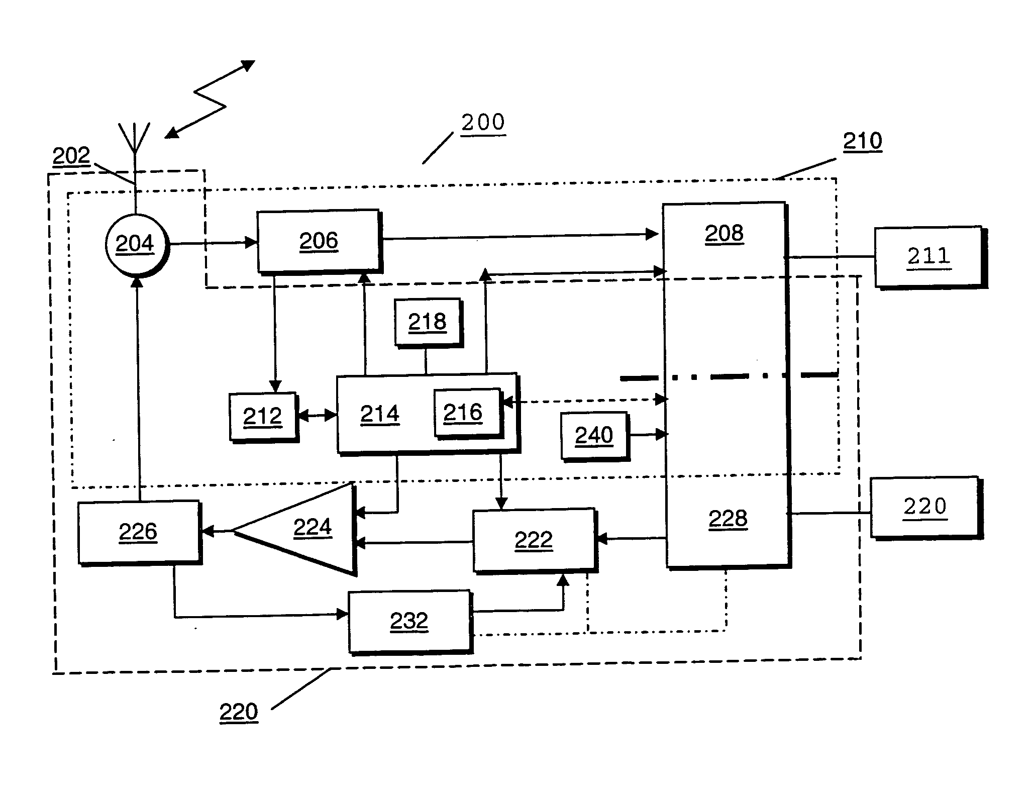
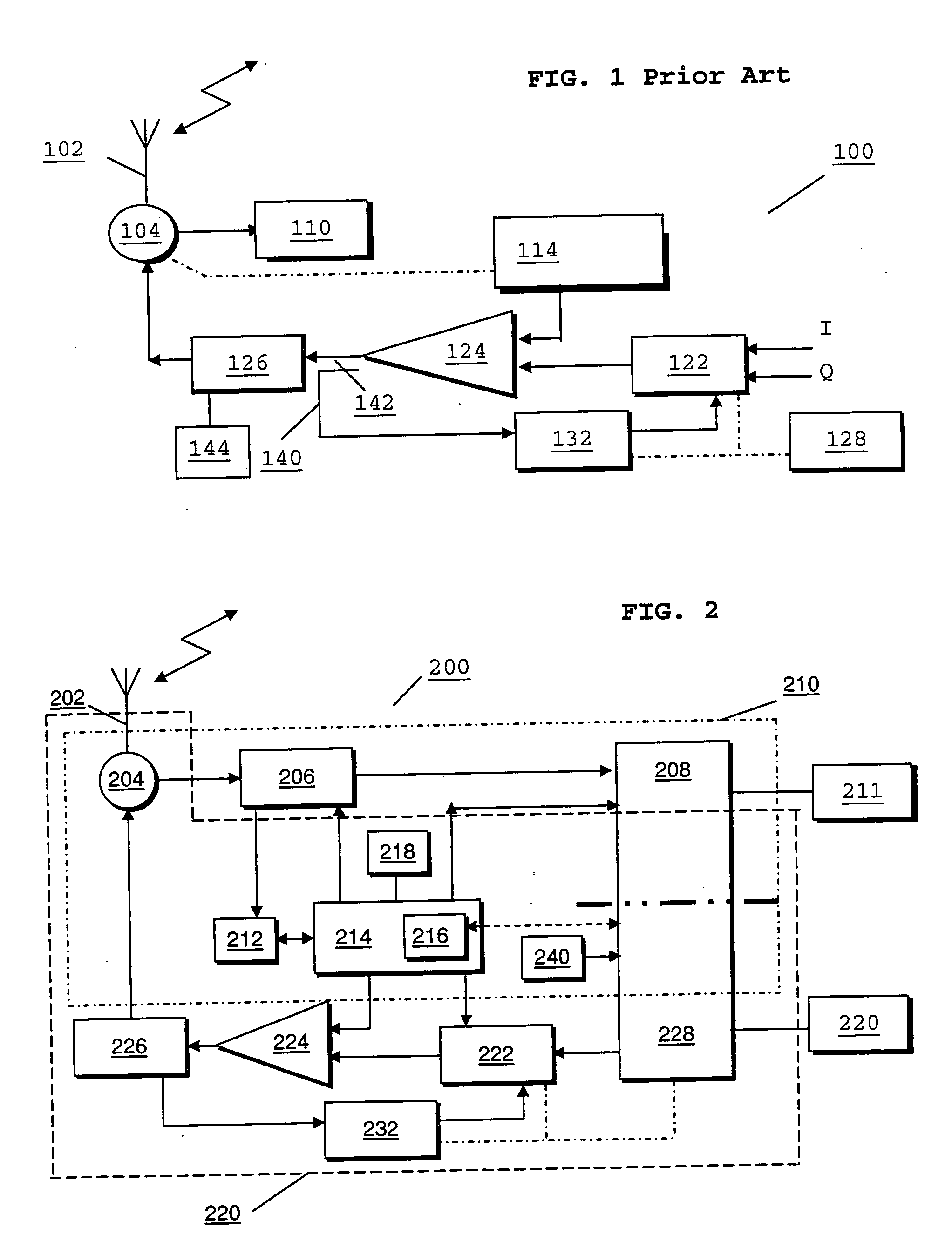
[0033] Referring now to FIG. 2, a block diagram of a wireless communication unit 200 adapted to support the inventive concepts of the preferred embodiments of the present invention, is illustrated. For the sake of clarity, the wireless communication unit 200 is shown as divided into two distinct portions — a receiver portion 210 and a transmitter portion 220.

[0034] The wireless communication unit 200 contains an antenna 202 preferably coupled to an antenna switch 204 that provides signal control of radio frequency (RF) signals in the wireless communication unit 200. The antenna switch 204 also provides isolation between the receiver 210 and transmitter chain 220. Clearly, the antenna switch 204 could be replaced with a duplex filter, for frequency duplex communication units as known to those skilled in the art.

[0035] For completeness, the receiver 210 of the wireless communication unit 200 will be briefly described. The receiver 210 includes a receiver front-end circuitry 206 (eff...


PUM


Abstract

A wireless subscriber communication unit (200) comprises an antenna arrangement (202, 330, 430) for radiating and/or receiving electromagnetic signals. A transmitter (220) and/or a receiver (210) is/are operably coupled to the antenna arrangement (202, 330, 430), for transmitting/receiving a radio signal. An antenna arrangement comprises an internal antenna located within the wireless communication unit (200) and an external antenna located substantially outside of the wireless communication unit, such that both the internal antenna (330, 430) and the external antenna (202) co-operate on substantially the same electromagnetic signal. In this manner, by provision of both an internal and an external antenna the wireless subscriber communication unit is able to function adequately should an antenna become disconnected, malfunction, or its performance suffer from impedance mismatching. Preferably, the internal and external antennas can be configured to be orthogonal to one another, thereby providing the wireless subscriber unit with the ability to operate with a substantially circular or elliptical polarization.

Description

FIELD OF THE INVENTION [0001] This invention relates to a wireless subscriber communication unit and antenna arrangement therefor. The invention is applicable to, but not limited to, a radio frequency arrangement providing two (or more) antennas that improve antenna performance of a wireless subscriber communication unit as well as increase return power isolation between the antennas and a radio transmitter therein. BACKGROUND OF THE INVENTION [0002] Wireless communication systems, for example cellular telephony or private mobile radio communication systems, typically provide for radio telecommunication links to be arranged between a plurality of base transceiver stations (BTSs) and a plurality of subscriber units, often termed mobile stations (MSs). The term mobile station generally includes both hand-portable and vehicular mounted radio units. Radio frequency (RF) transmitters are located in both BTSs and MSs in order to facilitate wireless communication between the communication ...

Claims


Application Information

Patent Timeline
IPC IPC(8): H01Q1/24H01Q21/28H04B7/06
CPCH01Q1/242H01Q21/28H04B7/0613H01Q21/24
Inventor GROSSMAN, OVADIABEN-AYUN, MOSHE
Owner MOTOROLA INC
Why Eureka
Try Eureka