Organic electroluminescence panel

a technology of electroluminescence panels and organs, applied in the direction of luminescence screens, discharge tubes, instruments, etc., can solve the problems of easy deformation of organic el elements by moisture and likely damage, and achieve the effects of convenient use, simple structure and large surface area

Inactive Publication Date: 2005-03-01
SANYO ELECTRIC CO LTD
View PDF7 Cites 24 Cited by
  • Summary
  • Abstract
  • Description
  • Claims
  • Application Information

AI Technical Summary

Benefits of technology

The present invention can provide an organic EL panel capable of suppressing adverse effects of panel flexure.
Thus, the thickness of the moisture absorbent in the inner region (the region distant from the peripheral portion connected to the EL substrate) is reduced, thereby maintaining a relatively large distance between the EL substrate and the sealing substrate. While the moisture absorbent is disposed with a thickness larger in a inner region than in the outer region, deformation is small in the outer region, so that contact between the moisture absorbent and the EL substrate due to flexure can efficiently be prevented.
Also in such a configuration where the moisture absorbent is disposed in a central region, contact between the moisture absorbent and the EL substrate can be prevented while maintaining sufficient moisture absorbing function by reducing the thickness of the moisture absorbent in this region as compared with that in the peripheral portion.
Such a spiral configuration of the moisture absorbent allows a moisture absorbent having a large surface area to be disposed in a minimum area.
As a result, a moisture absorbent having a large surface area can be efficiently provided in a limited area and with a simple structure.
As described above, because the moisture absorbent is not provided in the inner region, a large distance between the EL substrate and the sealing substrate can be maintained in this region. In addition, in an organic EL panel emitting light from the sealing substrate side to outside, the moisture absorbent can be provided on the sealing substrate without blocking light from the organic EL element, thereby preventing degradation due to moisture.

Problems solved by technology

This represents a disadvantage because such organic EL elements are relatively easily degraded by moisture.
Because the EL element is generally composed of an organic layer including an emissive layer between an anode and a cathode, and the cathode is often located at the upper surface of the EL element, the cathode is most likely to contact the moisture absorbent, and, because of its reduced thickness, damage is likely.

Method used


Image

  • Organic electroluminescence panel
  • Organic electroluminescence panel
  • Organic electroluminescence panel

Examples


Embodiment Construction

Preferred embodiments of the present invention will now be described with reference to the accompanying drawings.

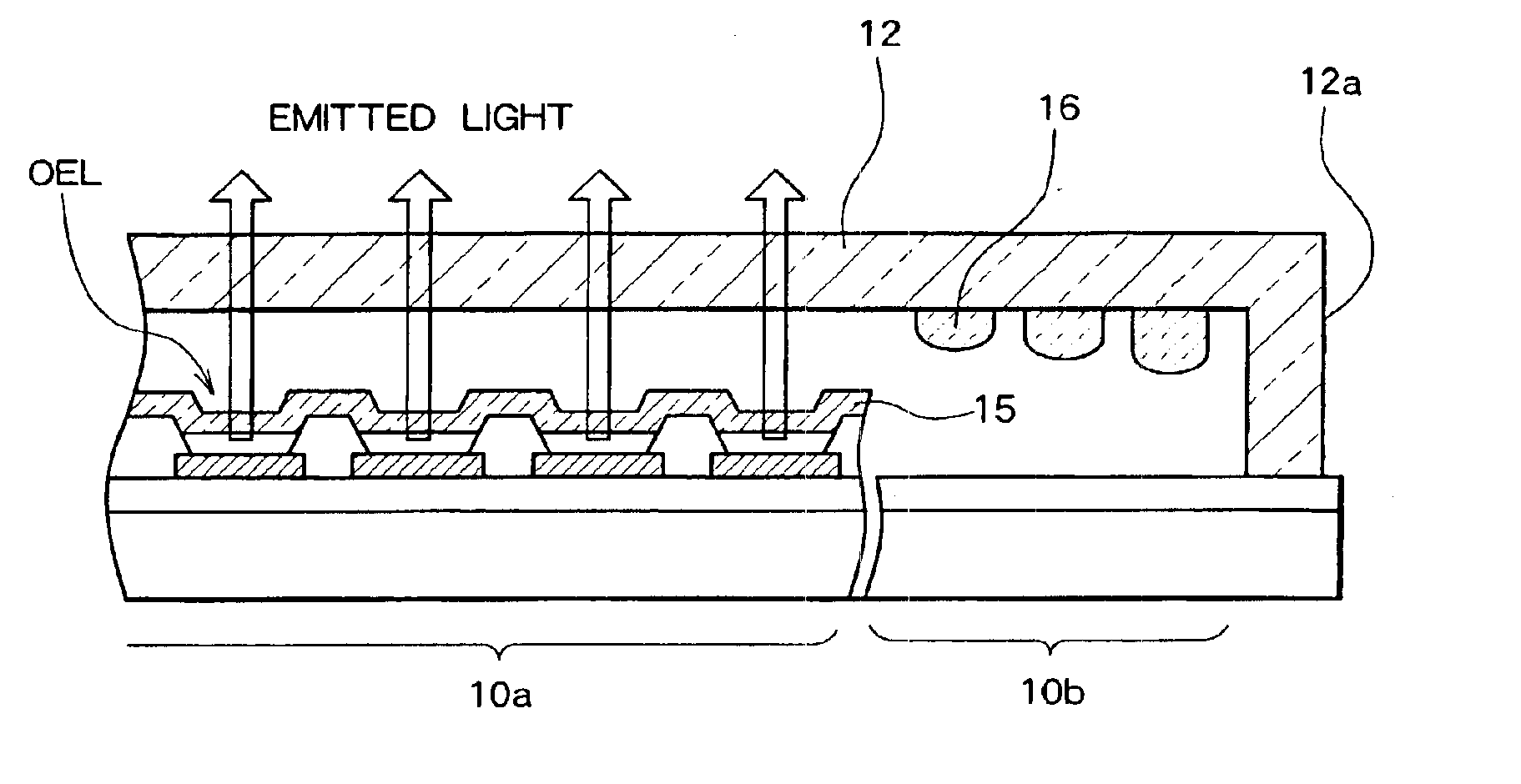
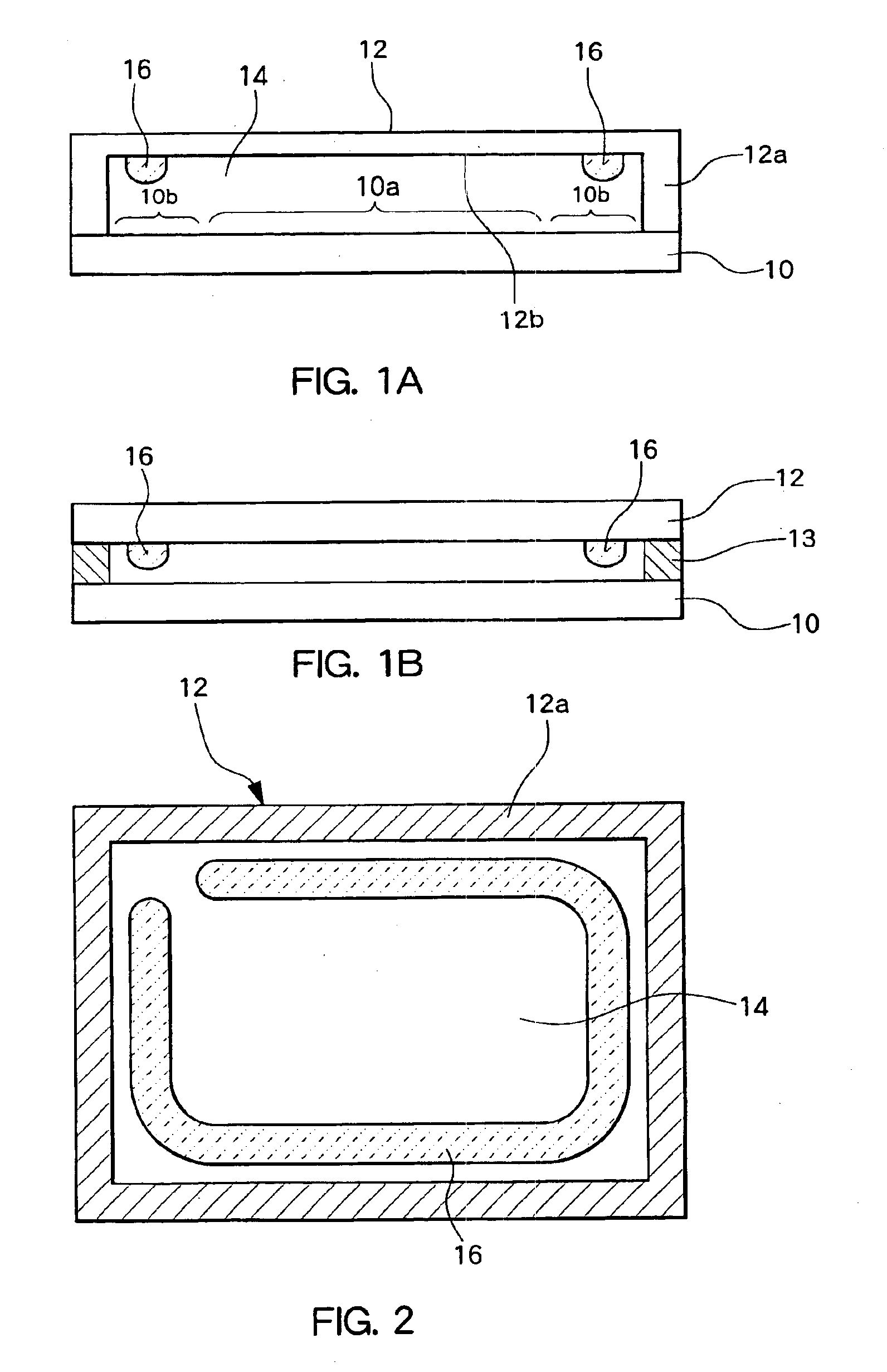
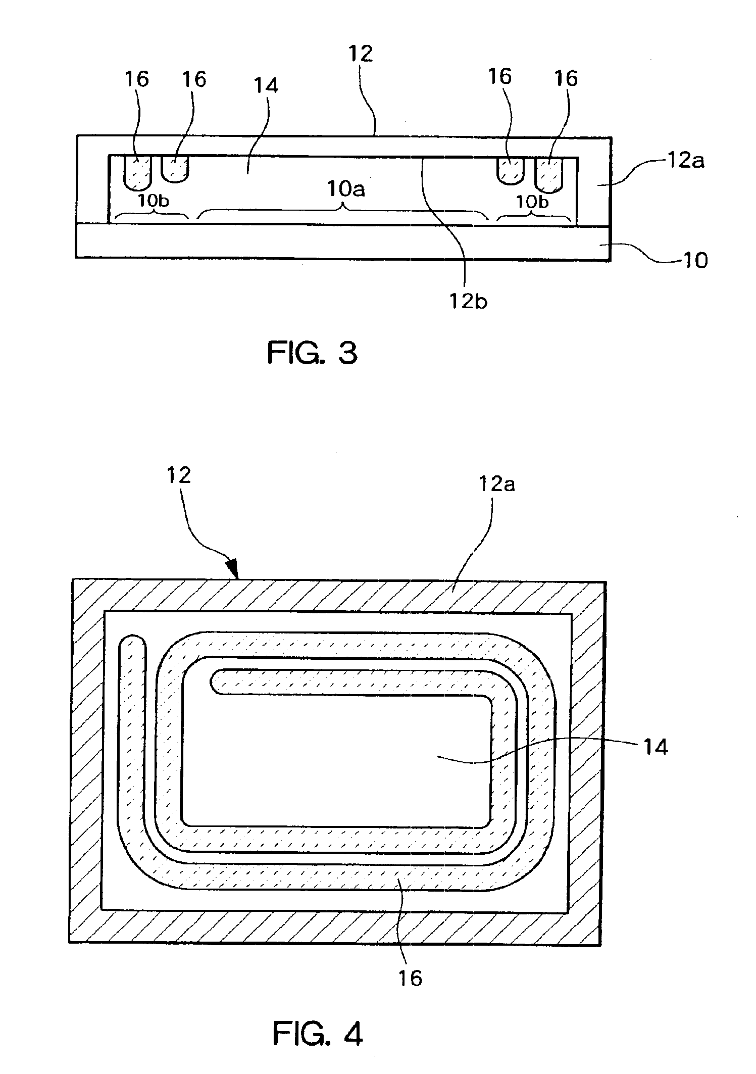
FIGS. 1A and 1B and FIG. 2 schematically illustrate a configuration of one embodiment according to the present invention. Referring to FIG. 1A, on an EL substrate 10 a concave sealing substrate 12 is disposed such that only the peripheral portion contacts the substrate 10, and such that an inner portion located above the substrate provides a predetermined distance between the substrates. In other words, the peripheral portion of the sealing substrate 12 is formed as a frame 12a projecting toward the EL substrate 10, and only the tip portion of the frame 12a contacts the surface of the EL substrate 10. The contacting portion is bonded to the substrate with a sealing agent, thereby sealing an inner space 14 off from the outside. The concave portion of the sealing substrate 12 is provided corresponding to the region where a plurality of display pixels including the organic E...


PUM


Abstract

A sealing substrate is disposed opposite an EL substrate. A frame in the peripheral portion of the sealing substrate is connected to the peripheral portion of the EL substrate to seal off an inner space. A desiccant (moisture absorbent) is provided on the inner space of the sealing substrate. Further, the thickness of the desiccant is smaller in a region distant from the frame (near the center of the substrate) than in a region near the frame, thereby preventing contact between the desiccant and the EL substrate.

Description

BACKGROUND OF THE INVENTION1. Field of the InventionThe present invention relates to organic electroluminescence (EL) panels, and more particularly to an organic EL panel provided with a moisture absorbent for drying the space above organic EL pixels.2. Description of the Related ArtOrganic EL panels represent a type of flat display panel under active development. In an organic EL panel, an organic EL element is used for each pixel. This represents a disadvantage because such organic EL elements are relatively easily degraded by moisture.To deal with this disadvantage, it is common for a surface of an organic EL substrate having organic EL elements arranged thereon in a matrix to be covered with a concave sealing substrate, to seal off the space above the organic EL elements and prevent the entry of moisture. Additionally, in order to remove any moisture entering inside, it is common for a moisture absorbent to be applied on an inner upper surface of the sealing substrate.EL substra...

Claims


Application Information

Patent Timeline
Patent Type & Authority Patents(United States)
IPC IPC(8): H01L51/52H01L51/50H05B33/04H05B33/14
CPCH01L51/5237H10K59/874H05B33/04H10K50/846
Inventor HISHIDA, MITSUOKI
Owner SANYO ELECTRIC CO LTD
Why Eureka
Try Eureka